HITEC OPTIC 6 Sport Instruction Manual Download Page 14

Page 25

Page 26

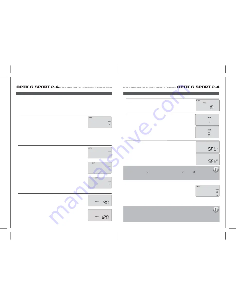
1. Select a model slot:

4. Configure the countdown timer:

2. Select the Model type programming baseline:

3. Heli Swash Plate:

Before you turn on the transmitter to begin programming one of the model slots for your aircraft, refer to the servo connection chart on page 12, 
to see how to plug the servos into their proper channel sockets in the receiver.

Don't turn on the receiver in your model just yet - we'll tell you when to do so. 
First we'll get started setting up the aircraft in the Initial Setup program menu, then we'll continue into 
the Main Function menu to configure the servo responses and travels of your particular model. 

Hold down both EDIT buttons and slide the on-off switch to "on". 
The transmitter will beep, the red light will come on, and on the LCD screen you will find yourself in the 
first menu item of the initial setup menu. 
Under the word "MODEL" the number will be blinking on and off to get your attention. 
If this is the first model you are setting up in this transmitter, go ahead and accept this numbered slot by 
pushing the right-hand EDIT button to scroll down to the next menu item. 
When there are already models inputted, the number that comes up when you turn on the transmitter 
will be the last activated model slot. 
To change to a different slot, push on one of the CURSOR buttons to go to an empty slot 
(consult your list!) and then scroll to the next screen to automatically select it.

In the second menu screen, the programming baseline of ACRO, GLID, or HELI will be blinking. 
Since we are setting up a powered aircraft, select ACRO by scrolling to it with a CURSOR button. 
Push down both DATA buttons simultaneously to tell the program to accept the choice-you should 
hear the transmitter beep twice in acknowledgement.
Now push the right-hand EDIT button to move to the next menu screen.

If you selected HELI as your model type, this screen will appear allowing you to select between 
NORMAL (90 degree mechanical) or 120 degree swash plate heli's by pressing one of the 
CURSOR buttons.
Find out which one of these popular swash formats your helicopter uses and select it here. 
After selecting the appropriate swash type, continue down to the next menu item.

Initial Setup Menu Programming for All Aircraft

Initial Setup Menu Programming for All Aircraft

Now you are at the TIMER menu item with a number blinking away at you-its 10 (minutes) by default. 
If you want to set a timer value, go to page 12 for more information on using the timer function. 
Otherwise, move down to the next menu item. 

5. Select the control's Mode configuration: 

6. Select the signal shift: 

Under the word "MODE", the number "2" is blinking by default. 
Go ahead and accept mode 2 by pushing the right-hand EDIT button to continue to the next screen.
Of course, if you are used to the mode 1 configuration (elevator on the left stick, throttle on the right), 
then select number 1. Other changes to accommodate Mode 1 flyers must be done to the transmitter. 
Please refer to page 7 for more information.

As indicated by the "SFt" symbol on the screen we are now in the shift selection menu. 
The blinking default selection is "n", meaning negative shift. 
If your receiver is marked "positive" shift, push one of the CURSOR buttons so that a "P" starts blinking. 
Then scroll to the next screen.

7. Reset Screen: 

In this screen you should now see  a tiny "RST" blinking in the lower right hand corner This means 
RESET-and if you push both DATA buttons at the same time that's exactly what will happen: You will 
hear a "double beep" and undo all the initial programming we just did, returning all the programming to 
the factory's default settings!

Now push the Right EDIT button to scroll right back where we started when we first turned on the transmitter. 
We are now done with the initial setup programming of your aircraft, so switch off the transmitter. 
When you switch it on again without holding down both EDIT buttons the transmitter will open up in the current model slot (the one we just 
programmed) with all the initial settings we just programmed in effect.

The Optic Sport features a powerful option allowing you to select between a Negative or Positive signal 
transmit shift. This allows you to use any brand of  modern FM receiver. 
As a general rule, Futaba R  receivers are "Negative" shift, while JR R , Airtronics R and most Multiplex 
receivers are all Positive shift. 
All models of  Hitec receivers have been offered in both shift versions, while newer Hitec receivers are now 
"auto shift selectable" and automatically know what shift the transmitter is. 

At this point you have selected the type of  model ACRO, GLID or HELI, you wish to set-up. 
In the manual text that follows, we will review and explain the Model Setup Menu of  the three different 
model types. 
The first is ACRO, followed by GLID, then HELI. All ACRO features will be described in detail within the ACRO section. 
Within the following GLID and HELI sections, only features exclusive to GLID and HELI programming will be 
described in detail. 
For those GLID and HELI features common to ACRO, we will refer you to their description within the ACRO section.

Summary of Contents for OPTIC 6 Sport

Page 1: ...AL COMPUTER RADIO SYSTEM SYSTEM 2 4 Function Assignable Switches Easy to Read LCD Screen Bulit in Hitec AFHSS 2 4GHz System INSTRUCTION MANUAL 0678 6CH 2 4GHz DIGITAL COMPUTER RADIO SYSTEM 2 4 Made in...

Page 2: ...C 6 SPORT 2 4 is your first programmable radio control transmitter you re probably feeling a bit overwhelmed by all the buttons and switches on the case and the cryptic symbols that appear on the radi...

Page 3: ...emperature extremes For protection wrap the receiver in the provided Flight Preserver foam rubber or use some other vibration absorbing materials If your flying near bodies of water it s also a good i...

Page 4: ...ally power on the STUDENT transmitter Though it is powered on the STUDENT transmitter will not transmit the radio signal as long as the trainer cable is connected properly 1 To use the trainer system...

Page 5: ...n their vicinity Flying Safety Stick Length Adjustment You may adjust the stick tension of your sticks to provide the feel that you like for flying To adjust your springs you ll have to remove the rea...

Page 6: ...of using this function whenever you are carrying your model to the flight line LOCK button KEEP YOUR HANDS AWAY FROM THE PROPELLER OR ROTORS EVEN AFTER ENABLING THE LOCK FUNCTION A RADIO GLITCH COULD...

Page 7: ...with Dual LED indicator has two colored LEDs blue and red for status indication and for set up process indication of 2 4GHz system This function button can be used for Link ID Setting process between...

Page 8: ...on is easy and simple insert the antenna into the supported Antenna holder and stick it to the desired spot you wish to install Optima 6 Receiver Features Optima Receiver Connection Diagrams Follow th...

Page 9: ...e are available 2 4GHz channels that can be used by your Hitec AFHSS 2 4 system The following will explain how Normal Mode and Scan Mode use the channels Normal Mode In this mode the receiver transmit...

Page 10: ...switch to Scan Mode noted by the blue and red LED and one beep Switching from Normal Mode to Scan Mode 1Sec 3Sec 3Sec Turn on transmitter then the receiver You will hear two short beep sound for Scan...

Page 11: ...ivers into other aircraft to be controlled by your Aurora Note both module and receiver need to re boot turn the power off and back on FAIL SAFE and Hold Mode FAIL SAFE Setup If you use the FAIL SAFE...

Page 12: ...a regulator set up or a commercially available BEC with enough capacity 3A or more capacity is recommended The SPC system was partially created to be integrated into future Hitec telemetry system devi...

Page 13: ...symbol in the black box at the bottom of the screen indicates which switch SW1 or SW3 needs to be reset to Normal Rx Ch ACRO GLID HELI Aileron Aileron Roll Cyclic One or Right Flaperon FLPN ON or Rig...

Page 14: ...information on using the timer function Otherwise move down to the next menu item 5 Select the control s Mode configuration 6 Select the signal shift Under the word MODE the number 2 is blinking by d...

Page 15: ...itial setup menu Go ahead and switch the transmitter on you are now in the standard operating screen In the upper left hand corner it will say ACRO and to the right there will be a large number tellin...

Page 16: ...direction The EPA function is normally used to prevent any servos from binding at the ends of their travel 1 To set the RIGHT TURN aileron motion which is upward on the right wing and downward on the...

Page 17: ...blinking if it isn t already by default The default value showing on the screen should be 100 but notice the extra little zero next to the 100 This indicates that the rate is this value 100 when the s...

Page 18: ...o servos simultaneously This is especially useful if you are using two elevator servos one to each half of the elevator In flight if the elevator needs to be trimmed you can make the adjustment with t...

Page 19: ...a rudder control to the aileron stick movement refer to the Aileron Rudder mix on page 26 Use a small percentage of mix for coordinated turns or set it up at 100 mix if your plane does not have ailero...

Page 20: ...buttons simultaneously Now we are ready to feed in values for the ailerons and elevator for pitch compensation when you pull the switch toward you You could of course choose to activate the mode with...

Page 21: ...der the default value of 100 If it isn t you can return to the default value immediately by pressing the Clear button Next to the 100 a 0 indicates that switch SW 2 is in the 0 position if it isn t pu...

Page 22: ...back to this section when you are ready to begin the setup 1 Start with the correct model type GLID in the Initial Setup Menu 2 Access the main programming menu then use the REV function and make sure...

Page 23: ...ints inside circle Too much coupling or differential Reduce one or both ADIF Aileron Differential Initial Menu Feature Review for GLID Programming The following item is located in the Initial Menu as...

Page 24: ...on CH 6 to 75 of their travel If you have two flap servos they should be connected with a Y harness to the channel 6 slot on the receiver 4 Finally curser to CH 2 and set the elevator travel value so...

Page 25: ...smitters in the gyro s manual 7 Program 35 EXPO values for Roll Ch 1 and Pitch Ch 2 8 After your heli is all ready to fly put it on a shelf and go get an R C flight simulator program for your PC Spend...

Page 26: ...this menu you can program specific control functions and the value the amount of servo travel for the particular model helicopter you selected earlier in the initial setup menu Go ahead and switch th...

Page 27: ...ttle hold 3 You begin a point 1 which will be blinking This is the idle position and will have a default value of 0 Press the DATA Increase or Decrease button to change the setting to your desired val...

Page 28: ...type does contain the SWAH menu The swash default settings are shown below The Throttle Hold function moves the engine throttle servo to a selected position near idle and disengages it from the throt...

Page 29: ...aileron 7 If all the servos tilt the swash aft with up elevator stick go to the next step If they tilt the swash forwards press the CURSOR Right button once to get to the elevator setting menu the arr...

Page 30: ...E CH5 ON INH ON INH ON INH NOR ST1 ST2 ST3 V TAL A R E F CROW CAMB ADIF FLT C TIMER MODE ON INH TRM 0 1 0 1 D R EXP S TRM S REV ELEV CH2 ELEV CH4 RUDD CH4 RUDD CH2 MODEL TYPE HELI SFT N P MODEL NAME 0...

Reviews: