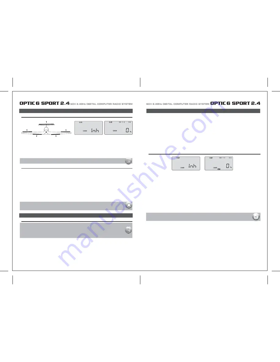
HITEC OPTIC 6 Sport Instruction Manual Download Page 24

Page  45

Page 46

Setting Up CROW

CAMB (Wing Camber) 

Setting Up Flight Mode Wing Camber and Elevator Compensation

CROW  (Glide-Path and Airspeed Control)

CAMB (Wing Camber) 

1. The first step is to leave this screen and move down to the Flight Condition (FLT C) screen in order to put the wing camber and elevator 
    action of each mode on the three-position SW-3 "FLT Mode" switch on the upper right-hand top of the transmitter case. 
    Use the Right EDIT button to move down to the FLT C screen.

2. Now activate what will be the "launch" mode by moving the switch position toward you and then hitting both DATA buttons. 
    The "Inh" symbol will change to "On" and ST2 will be blinking. 
    Move the switch all the way back and, in the same way, activate switch position ST1 which will  become our "thermal" mode. 
    The middle, normal position (NOR) is "cruise". 
    You can, of course, reverse the launch and thermal positions to what  feels intuitive to you.

3. Now scroll back up to the CAMB screen with an EDIT button and move the switch SW-3 toward you to the "launch" mode position. 
    Turn your model on so you can watch the control surfaces move. 

4. With CH 1 blinking, change the servo's travel value with a DATA button until the right wing's aileron comes up to the airfoil's reflex position. 

Launch: 
When switch SW-3 is pulled toward you the ailerons and flaps will rise together slightly to "reflex" the airfoil for high-speed flight and the 
elevator will kick up a few degrees to rotate the model vertical in the first 5 seconds or so of flight. 

Cruise: 
When you push switch SW-3 to the middle position, the ailerons and flaps will come even with the trailing edge and the elevator will move 
down very slightly (relative to its normal angle of incidence). This allows the glider to quickly fly between thermals and through areas of sink. 

Thermal:  
With the SW-3 switch pushed away from you, the ailerons and flaps will droop down 3/6-in. and the elevator will come up a few degrees from 
its normal angle of incidence.
This is the mode to be in when you suspect you have hooked into a thermal. The glider is now at its lowest sink rate and can fly just above a 
stall to allow you to turn tightly and keep in the small core of the thermal. 

CROW  (Glide-Path and Airspeed Control)

(CROW raises the ailerons and lowers the flaps when you move  the left-hand joystick toward the bottom of the transmitter case) 

1) Activate the function by pressing both DATA buttons simultaneously. 
2) Watching the motion of the control surfaces on your model, set the value for each of the servos with the left-hand joystick pulled all the 
    way to the bottom of the transmitter case. 
    Begin with the aileron servos in CH 1 and CH 5: Unless the servos buzz and stall, set both ailerons to rise to approxamatly 50% of their 
    travel. 
    Don't make this value too large, as you still need to control the aircraft's roll rate with the ailerons.
    upward (Note that you can go to a negative value % to reverse the direction of the movement of one of the aileron servos if necessary).
3) Set the flap servo on CH 6 to 75% of their travel (If you have two flap servos, they should be connected with a Y-harness to the channel 6 
    slot on the receiver)
4) Finally, curser to CH 2 and set the elevator travel value so the elevator moves down just a bit for pitch control: 15% is a good starting point, 
    though in-flight testing is necessary for making true, final adjustments. 

SAFETY WARNING:  When checking out the in-flight response of  your model to the crow settings, 
be sure to first gain at least 200 feet of  altitude to allow time for you to recover from any loss of  control.

When flying gliders featuring modern, thin airfoils the ability to change the shape of the airfoil by reflexing (raising) or cambering (lowering) 
the trailing edge in combination with making simultaneous, slight changes in elevator trim is crucial to optimizing the performance of the 
model in a variety of flight conditions and tasks. 
The Optic Sport offers a selection of up to four flight condition modes in which you can program varying amounts of aileron, flap and elevator 
trim (as well as dual-rate and exponential values). 
These modes are activated by either switch SW-3 or SW-1. 

A typical example for setting up a discus-launched glider for optimum performance would consist of these three flight modes 
(which are all assigned to SW-3):

You must have A.DIF activated for ch. 5 to appear on the CROW screen

In this screen you can activate the CROW air-brake and glide path control function and set the values for the aileron, flap and elevator servo 
movements. The more CROW you apply during the landing approach (with the left-hand joystick), the more the glide path steepens and the 
glider slows down. 
Because you can regulate the amount of CROW, you can precisely control where and how slowly the glider lands-an important factor for 
landing on limited-length runways (gliders are generally a lot more "slippery" than power planes!) and in contests where you are rewarded 
points for landing on a target. 

CAMB (Wing Camber) 

While the Camber function also appears in the ACRO menu, the use of  this feature is significantly 
different for Sailplanes than it is with Power planes. Please refer to the instructions below to 
understand how to make the most effective use of  Camber on your Sailplane.

A solid understanding of  the Flight condition feature will help when programming wing Camber.

5. Using the right-hand CURSOR button, move to CH 2 and adjust the travel of the elevator upward a few degrees. 
    CURSOR to CH 6 and reflex the left wing's aileron. 
    If your trailing edge also has flaps, CURSOR to CH 5 and change their value to match that of the ailerons.  

6. Now move switch SW-3 to the center, normal position and follow the same process to set the trailing edge control surfaces and the elevator
    to the appropriate values for the "cruise" mode. 

7. Finally, move SW-3 to the thermal position and adjust all the values there.
    When done, move away from this screen and/or turn off the transmitter. 
    As always, plan on adjusting the trailing edge and elevator settings in the CAMB screen after flight testing to optimize their affect on 
    performance.     

Note: Ask the manufacturer of  your glider for their recommendation for reflex-and 
          thermal-trailing edge positions. 

Summary of Contents for OPTIC 6 Sport

Page 1: ...AL COMPUTER RADIO SYSTEM SYSTEM 2 4 Function Assignable Switches Easy to Read LCD Screen Bulit in Hitec AFHSS 2 4GHz System INSTRUCTION MANUAL 0678 6CH 2 4GHz DIGITAL COMPUTER RADIO SYSTEM 2 4 Made in...

Page 2: ...C 6 SPORT 2 4 is your first programmable radio control transmitter you re probably feeling a bit overwhelmed by all the buttons and switches on the case and the cryptic symbols that appear on the radi...

Page 3: ...emperature extremes For protection wrap the receiver in the provided Flight Preserver foam rubber or use some other vibration absorbing materials If your flying near bodies of water it s also a good i...

Page 4: ...ally power on the STUDENT transmitter Though it is powered on the STUDENT transmitter will not transmit the radio signal as long as the trainer cable is connected properly 1 To use the trainer system...

Page 5: ...n their vicinity Flying Safety Stick Length Adjustment You may adjust the stick tension of your sticks to provide the feel that you like for flying To adjust your springs you ll have to remove the rea...

Page 6: ...of using this function whenever you are carrying your model to the flight line LOCK button KEEP YOUR HANDS AWAY FROM THE PROPELLER OR ROTORS EVEN AFTER ENABLING THE LOCK FUNCTION A RADIO GLITCH COULD...

Page 7: ...with Dual LED indicator has two colored LEDs blue and red for status indication and for set up process indication of 2 4GHz system This function button can be used for Link ID Setting process between...

Page 8: ...on is easy and simple insert the antenna into the supported Antenna holder and stick it to the desired spot you wish to install Optima 6 Receiver Features Optima Receiver Connection Diagrams Follow th...

Page 9: ...e are available 2 4GHz channels that can be used by your Hitec AFHSS 2 4 system The following will explain how Normal Mode and Scan Mode use the channels Normal Mode In this mode the receiver transmit...

Page 10: ...switch to Scan Mode noted by the blue and red LED and one beep Switching from Normal Mode to Scan Mode 1Sec 3Sec 3Sec Turn on transmitter then the receiver You will hear two short beep sound for Scan...

Page 11: ...ivers into other aircraft to be controlled by your Aurora Note both module and receiver need to re boot turn the power off and back on FAIL SAFE and Hold Mode FAIL SAFE Setup If you use the FAIL SAFE...

Page 12: ...a regulator set up or a commercially available BEC with enough capacity 3A or more capacity is recommended The SPC system was partially created to be integrated into future Hitec telemetry system devi...

Page 13: ...symbol in the black box at the bottom of the screen indicates which switch SW1 or SW3 needs to be reset to Normal Rx Ch ACRO GLID HELI Aileron Aileron Roll Cyclic One or Right Flaperon FLPN ON or Rig...

Page 14: ...information on using the timer function Otherwise move down to the next menu item 5 Select the control s Mode configuration 6 Select the signal shift Under the word MODE the number 2 is blinking by d...

Page 15: ...itial setup menu Go ahead and switch the transmitter on you are now in the standard operating screen In the upper left hand corner it will say ACRO and to the right there will be a large number tellin...

Page 16: ...direction The EPA function is normally used to prevent any servos from binding at the ends of their travel 1 To set the RIGHT TURN aileron motion which is upward on the right wing and downward on the...

Page 17: ...blinking if it isn t already by default The default value showing on the screen should be 100 but notice the extra little zero next to the 100 This indicates that the rate is this value 100 when the s...

Page 18: ...o servos simultaneously This is especially useful if you are using two elevator servos one to each half of the elevator In flight if the elevator needs to be trimmed you can make the adjustment with t...

Page 19: ...a rudder control to the aileron stick movement refer to the Aileron Rudder mix on page 26 Use a small percentage of mix for coordinated turns or set it up at 100 mix if your plane does not have ailero...

Page 20: ...buttons simultaneously Now we are ready to feed in values for the ailerons and elevator for pitch compensation when you pull the switch toward you You could of course choose to activate the mode with...

Page 21: ...der the default value of 100 If it isn t you can return to the default value immediately by pressing the Clear button Next to the 100 a 0 indicates that switch SW 2 is in the 0 position if it isn t pu...

Page 22: ...back to this section when you are ready to begin the setup 1 Start with the correct model type GLID in the Initial Setup Menu 2 Access the main programming menu then use the REV function and make sure...

Page 23: ...ints inside circle Too much coupling or differential Reduce one or both ADIF Aileron Differential Initial Menu Feature Review for GLID Programming The following item is located in the Initial Menu as...

Page 24: ...on CH 6 to 75 of their travel If you have two flap servos they should be connected with a Y harness to the channel 6 slot on the receiver 4 Finally curser to CH 2 and set the elevator travel value so...

Page 25: ...smitters in the gyro s manual 7 Program 35 EXPO values for Roll Ch 1 and Pitch Ch 2 8 After your heli is all ready to fly put it on a shelf and go get an R C flight simulator program for your PC Spend...

Page 26: ...this menu you can program specific control functions and the value the amount of servo travel for the particular model helicopter you selected earlier in the initial setup menu Go ahead and switch th...

Page 27: ...ttle hold 3 You begin a point 1 which will be blinking This is the idle position and will have a default value of 0 Press the DATA Increase or Decrease button to change the setting to your desired val...

Page 28: ...type does contain the SWAH menu The swash default settings are shown below The Throttle Hold function moves the engine throttle servo to a selected position near idle and disengages it from the throt...

Page 29: ...aileron 7 If all the servos tilt the swash aft with up elevator stick go to the next step If they tilt the swash forwards press the CURSOR Right button once to get to the elevator setting menu the arr...

Page 30: ...E CH5 ON INH ON INH ON INH NOR ST1 ST2 ST3 V TAL A R E F CROW CAMB ADIF FLT C TIMER MODE ON INH TRM 0 1 0 1 D R EXP S TRM S REV ELEV CH2 ELEV CH4 RUDD CH4 RUDD CH2 MODEL TYPE HELI SFT N P MODEL NAME 0...

Reviews: