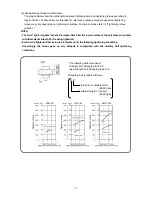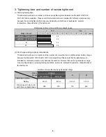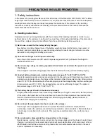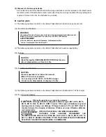
-17-
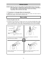
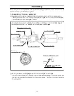
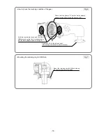
Push the internal wire (black) in securely so that the internal wire
(black) is not placed on the boss rib seat of the pushing button.
Internal wire (Red)
Housing (A)
Motor shaft
Internal wire (Black)
Do not contact the motor shaft.
Boss rib seat of the
pushing button
2. Reassembly of the hammer assembly
(1) Put Washer (S)
[15]
onto the shaft of the Spindle
[18]
and mount Hammer (A)
[11]
containing the
twenty-four Steel Balls D3.175
[12]
, Washer (J)
[13]
and Hammer Spring
[14]
to the Spindle
[18]
.
(2) Align the top of the cam groove on the Spindle
[18]
with the steel ball guide groove on Hammer (A)
[11]
.
Press down either of the raised faces of Hammer (A)
[11]
with a hand press to compress the Hammer
Spring
[14]
until the end surface of the hammer contacts the flange of the Spindle
[18]
.
(3) Insert the two Steel Balls D4.76
[17]
into the steel ball guide groove. Check that the Steel Balls D4.76
[17]
are properly inserted in the cam groove. Then release the hand press.
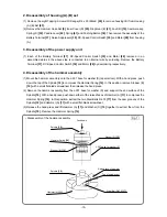
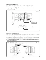
(4) Mount the hammer assembly onto the J-297 base for washer (S). With a hand press, push down the top
of the Spindle
[18]
to compress the Hammer Spring
[14]
. On this condition, mount Stopper (B)
[16]
onto
the spindle shaft and then release the hand press (Fig. 1).
(5) Mount the Idle Gear Set (2 pcs.)
[19]
and two Needle Rollers (A)
[20]
to the Spindle
[18]
and mount
Washer (E)
[22]
to it.
(6) Press-fit the Felt
[24]
and the Ball Bearing 6901VVCMPS2L
[23]
to Inner Cover (D)
[25]
.
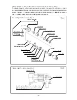
(7) (a) When using the Hammer Case Set
[5]
:
Mount Anvil (B)
[10]
, hammer assembly, Ring Gear (E)
[21]
and inner cover to the Hammer Case
[1]
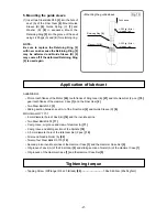
as shown in Fig. 4.
(b) When using the Hammer Case
[1]
and the Final Gear
[2]
:
Mount the Final Gear
[2]
to the Hammer Case
[1]
so that the Final Gear
[2]
is flush with the end face
of the Hammer Case
[1]
. Check that the gear meshes properly. Then press-fit the Final Gear
[2]
with
a hand press. Fit the Retaining Ring for D28 Hole
[4]
in the groove of the Hammer Case
[1]
being
careful of the mounting direction of the Retaining Ring for D28 Hole
[4]
(face the shear droop side to
the inside). Mount Anvil (B)
[10]
, hammer assembly, Ring Gear (E)
[21]
and inner cover to the
Hammer Case
[1]
in the same manner as the above step (a).
(8) Mount the Motor
[28]
to the above mechanical ass'y and mount it to housing (A). Check that the gears
of the motor pinion, Idle Gear Set
[19]
and Ring Gear (E)
[21]
turn smoothly. If not, the gears mesh
improperly. Check the meshing condition.
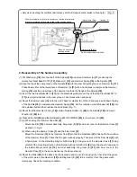
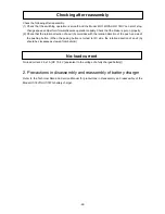
• Note when mounting the controller terminal ass'y and the DC-speed control switch to housing (A)
Fig. 3

