-21-
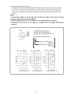
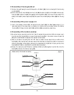
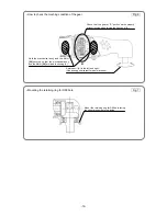
• Mounting the guide sleeve
Fig. 10
Push down
J-295 jig (B) for
retaining ring
J-295 jig (A) for
retaining ring
Retaining Ring
[9]
Washer (D)
[8]
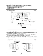
5. Mounting the guide sleeve
(1) Insert two Steel Balls D3.5
[3]
into the hole of
anvil (A) of the Final Gear
[2]
. Mount Guide
Sleeve (D)
[6]
, Guide Spring (C)
[7]
and
Washer (D)
[8]
in sequence. Mount the
Retaining Ring
[9]
into the groove of the anvil
using J-295 jigs (A) and (B) for retaining ring.
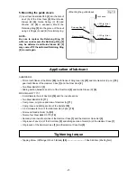
NOTE:
Be sure to replace the Retaining Ring [9]
with new one because the Retaining Ring [9]
may be deformed and Guide Sleeve (D) [6]
may come off if the deformed Retaining Ring
[9] is used again
.
ALBANIA RL3
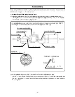
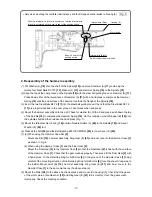
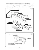
• Pinion tooth flanks of the Motor
[28]
, tooth flanks of Ring Gear (E)
[21]
and Idle Gear Set (2 pcs.)
[19]
,
gear tooth flanks of the Hammer Case
[1]
and the Final Gear
[2]
• Two Steel Balls D3.5
[3]
• Sliding section between anvil (A) of the Final Gear
[2]
and Guide Sleeve (D)
[6]
MOLUB-ALLOY 777-1
• 6 mm diameter hole of Anvil (B)
[10]
and the involute spline
• Two Steel Balls D4.76
[17]
• Cam groove, oil groove and claw of Hammer (A)
[11]
• Cam groove and sliding section of the Spindle
[18]
• 3.5 mm diameter hole of the Idle Gear Set (2 pcs.)
[19]
• All around Needle Roller (A)
[20]
• Twenty-four Steel Balls D3.175
[12]
• Second pinion involute splines of the Hammer Case
[1]
and the Hammer Case Set
[5]
• Oil groove of anvil (A) of the Final Gear
[2]
and sliding section of metal (A) of the Hammer Case
[1]
• Oil grooves of the Hammer Case
[1]
and the Hammer Case Set
[5]
• Tapping Screw (W/Flange) D4 x 20 (Black)
[26]
------------------------- 1.96±0.49 N
•
m {20±5 kgf
•
cm}
Application of lubricant
Tightening torque

