background image

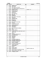
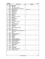
PARTS

WH 14DCAL

   DESCRIPTION

    REMARKS

1

329-672

HAMMER CASE

1

2

330-624

FINAL GEAR

1

3

319-535

STEEL BALL D3.5 (10 PCS.)

2

4

939-555

RETAINING RING FOR D28 HOLE (10 PCS.)

1

5

330-623

HAMMER CASE SET

1

INCLUD. 1, 2, 4

6

322-717

GUIDE SLEEVE (D)

1

7

330-617

GUIDE SPRING (C)

1

8

330-618

WASHER (D)

1

9

330-619

RETAINING RING

1

10

329-660

ANVIL (B)

1

11

329-665

HAMMER (A)

1

12

959-148

STEEL BALL D3.175 (10 PCS.)

24

13

329-617

WASHER (J)

1

14

329-658

HAMMER SPRING

1

15

329-614

WASHER (S)

1

16

329-613

STOPPER (B)

1

17

959-149

STEEL BALL D4.76 (10 PCS.)

2

18

329-659

SPINDLE

1

19

329-611

IDLE GEAR SET (2 PCS.)

2

20

329-612

NEEDLE ROLLER (A)

2

21

329-610

RING GEAR (E)

1

22

319-911

WASHER (E)

1

23

690-1VV

BALL BEARING 6901VVCMPS2L

1

24

329-518

FELT

1

25

329-657

INNER COVER (D)

1

26

301-653

TAPPING SCREW (W/FLANGE) D4X20 (BLACK)

8

27

NAME PLATE

1

28

329-669

MOTOR

1

29

329-671

INTERNAL WIRE (BLACK) 57L

1

30

329-656

PUSHING BUTTON

1

31

330-620

BUSHING (S)

1

32

330-621

SPRING (S)

1

33

330-622

TRIGGER

1

34

329-670

INTERNAL WIRE (RED) 36L

1

35

329-668

DC-SPEED CONTROL SWITCH

1

36

329-679

INTERNAL WIRE (RED) 26L

1

37

329-678

BATTERY TERMINAL

1

38

329-680

INTERNAL WIRE (BLACK) 52L

1

39

329-677

NOISE SUPPRESSOR

1

40

HITACHI LABEL

1

41

329-655

SPRING

1

42

329-654

PADDLE LEVER

1

*

43

306-952

STRAP (BLACK)

1

EXCEPT FOR USA, CAN

*

44

326-824

BATTERY BCL 1430 (EUROPE, AUS, NZL)

2

*

44

326-823

BATTERY BCL 1430 (USA, CAN)

2

45

329-676

HOUSING (A). (B) SET

1

- 2 -

8 - 08

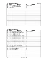
          *ALTERNATIVE PARTS

ITEM

NO.

NO.

USED

CODE NO.

Summary of Contents for WH 14DCAL

Page 1: ...the following 1 Compact body smallest center height in its class 16 5 mm 2 Newly structured paddle lever is very convenient With the new Models WH 14DCAL and WH 14DY we aim to expand our market share Tightening loosening of small screws tapping screws wood screws Teks screws Hex screws etc Tightening loosening of bolts nuts etc Drilling into wood and various other materials with use of the optiona...

Page 2: ...i com manual_view_export Throughout this TECHNICAL DATA AND SERVICE MANUAL a symbol s is are used in the place of company name s and model name s of our competitor s The symbol s utilized here is are as follows Competitors Symbols Utilized Company Name Model Name B MAKITA 6940DWA M MAKITA TL060DRF ...

Page 3: ...CAUTIONS IN SALES PROMOTION 9 1 Safety instructions 9 2 Tightening torque inspection prior to operation 11 3 Tightening torque variation 11 4 Precautions for efficient use of charger and battery 12 5 Other precautions 13 REPAIR GUIDE 14 1 Precautions in disassembly and reassembly 14 2 Precautions in disassembly and reassembly of battery charger 22 STANDARD REPAIR TIME UNIT SCHEDULES 23 Assembly di...

Page 4: ...th 392 370 387 Center height 16 5 17 5 18 Newly structured paddle lever Each of the Models WH 14DCAL and WH 14DY is equipped with the newly structured paddle lever for easier operation SELLING POINT DESCRIPTIONS Thanks to the paddle lever triggering speed change operation can be done reliably even by holding the upper portion base portion or any other portion of the housing The lock button prevent...

Page 5: ...ht 16 5 mm 21 32 Type of battery Sealed cylindrical lithium ion storage battery Nominal voltage DC 14 4 V Nominal life Charging discharging approximately 1 500 times Battery Type BCL 1430 Nominal capacity 3 0 Ah Charger Model UC 18YRL Overcharge protection system 1 Battery voltage detection ΔV system Battery temperature detection dT dt system for Ni MH and SUPER Ni MH batteries 2 Battery surface t...

Page 6: ...ross WH 14DY 2BGK 4 6 kg 10 1 lbs WH 14DY NN 1 3 kg 2 9 lbs Overall length x Head height 392 mm 15 7 16 x 53 mm 2 5 64 Center height 16 5 mm 21 32 Type of battery Sealed cylindrical Ni Cd storage battery Nominal voltage DC 14 4 V Nominal life Charging discharging approximately 1 000 times Battery Type EB 14B Nominal capacity 2 0 Ah Charger Model UC 18YG Overcharge prevention circuit A thermostat m...

Page 7: ...5329 65 2 9 16 10 3 8 5 16 hexagon socket 12 996178 65 2 9 16 12 15 32 8 mm hexagon socket 13 996179 65 2 9 16 13 1 2 10 mm hexagon socket small type 14 996180 65 2 9 16 14 9 16 10 mm hexagon socket 16 996181 65 2 9 16 16 5 8 10 mm hexagon socket 17 996182 65 2 9 16 17 21 32 3 Drill chuck adaptor set Code No 321823 The drill chuck adaptor set permits mounting of various types of locally available ...

Page 8: ...0 in lbs 60 531 in lbs 60 530 in lbs 61 539 in lbs No load speed min 1 0 to 2 100 0 to 2 000 0 to 2 000 Impact rate min 1 0 to 3 200 0 to 2 700 0 to 3 000 Main body weight kg 1 6 3 5 lbs 1 9 4 2 lbs 1 5 3 3 lbs 1 6 3 5 lbs Overall length mm 392 15 7 16 370 14 5 8 387 15 15 64 Head height mm 53 2 5 64 60 2 23 64 53 2 5 64 Center height mm 16 5 21 32 17 5 11 16 18 45 64 Type of switch Paddle lever P...

Page 9: ...ning torque kgf cm d Nominal diameter of thread mm p Recommended axial tightening force to be applied to the screw kgf p Rated axial stress kgf cm2 x 0 8 x Effective sectional area of the thread mm2 k Torque coefficient 0 17 Strength grade and rated axial stress of thread Strength grade 4 8 6 8 8 8 12 9 Rated axial stress kgf mm2 29 1 43 7 58 2 95 Material Mild steel Alloy steel including Ni Mn Cr...

Page 10: ...m tightening time means the impact time after the lower surface of the bolt comes in contact with the material into which it is being tightened Each bolt is tightened directly into a steel plate under the following tightening conditions Accordingly the torque goes up very abruptly in comparison with the ordinary bolt tightening conditions The following bolts were used Ordinary bolt Strength grade ...

Page 11: ... WH 14DCAL 3 0 HITACHI WH 14DY 3 0 B 3 2 M 3 6 2 Per charge working capacity comparisons The table below shows a comparison of the number of screws that can be tightened per battery charge between the Model WH 14DCAL WH 14DY and competitors Please note that the data below are intended for reference purposes only because the number of screws that can be tightened per charge may vary depending on sc...

Page 12: ...ambient temperature range of 0 to 50 C 32 F to 122 F Special temperature sensitive devices are employed in the charger to permit rapid charging Ensure that customers are instructed to use the charger at the indicated ambient temperature range At temperature under 0 C 32 F the thermostat will not function properly and the storage battery may be overcharged At temperature over 40 C 104 F the storage...

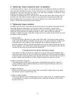
Page 13: ...ENT ECLATER ET CAUSER DES BLESSURES OU DOMMAGES CAUTION AVERTISSEMENT ATTENTION WARNING To reduce the risk of injury user must read and understand instruction manual Risk of fire burn or explosion For use only with BCL 1430 battery AVERTISSEMENT Afin de réduire le risque de blessures l utilisateur doit lire et bien comprendre le mode d emploi 8 Disposal of the storage batteries Ensure that all cus...

Page 14: ...ue decreases as the number of bolts tightened increases This phenomenon is caused by the decline in voltage output of the battery due to the increasing number of bolts tightened In particular the tightening torque decreases rapidly just before the overdischarge protection circuit is activated As this phenomenon is an inherent drawback in any cordless impact driver wrench salespersons are requested...

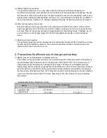
Page 15: ...ng torque that can be achieved may be considerably decreased if the bolt and the nut rotate together during the tightening operation The customers should be advised to carefully observe the operation and ensure this does not occur 4 Precautions for efficient use of charger and battery 1 Battery may not be rechargeable immediately after use If the battery is exposed to direct sunshine for an extend...

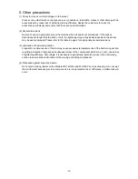
Page 16: ...cket may be easily damaged Please refer to the table in page 4 for appropriate socket dimensions 3 Lubrication of hammering section Frequent or continuous use of the tool may cause excessive temperature rise of the hammering section resulting in depletion of grease and subsequent wear of the components which may in turn cause loss of tightening efficiency Accordingly it is necessary to periodicall...

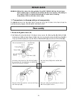
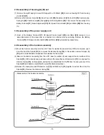
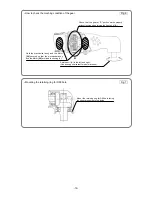
Page 17: ...the Retaining Ring 9 Washer D 8 Guide Spring C 7 and Guide Sleeve D 6 in this order Avoid quickly raising the Retaining Ring 9 or it may fly out forcefully Be sure not to lose the two Steel Balls D3 5 3 in anvil A of the Final Gear 2 Disassembly REPAIR GUIDE Hold the body and adjust the gap of the Retaining Ring 9 to the groove of anvil A then insert the tip of a small flat blade screwdriver into ...

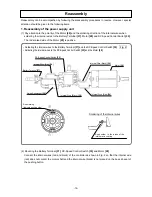
Page 18: ...ed status in the above step is connected to an internal wire by soldering Remove the Battery Terminal 37 DC Speed Control Switch 35 and Motor 28 by desoldering respectively 4 Disassembly of the hammer assembly 1 Mount the hammer assembly onto the J 297 base for washer S special tool With a hand press push down the top of the Spindle 18 to compress the Hammer Spring 14 In this position remove Stopp...

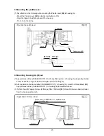
Page 19: ...llowing the disassembly procedures in reverse However special attention should be given to the following items 1 Reassembly of the power supply unit 1 Pay attention to the polarity of the Motor 28 and the soldering direction of the internal wires when soldering the internal wires to the Battery Terminal 37 Motor 28 and DC Speed Control Switch 35 The red marked side of the Motor 28 is positive 2 Mo...

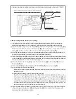
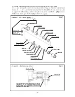
Page 20: ...opper B 16 onto the spindle shaft and then release the hand press Fig 1 5 Mount the Idle Gear Set 2 pcs 19 and two Needle Rollers A 20 to the Spindle 18 and mount Washer E 22 to it 6 Press fit the Felt 24 and the Ball Bearing 6901VVCMPS2L 23 to Inner Cover D 25 7 a When using the Hammer Case Set 5 Mount Anvil B 10 hammer assembly Ring Gear E 21 and inner cover to the Hammer Case 1 as shown in Fig ...

Page 21: ...r A 20 Ring Gear E 21 Washer E 22 Ball Bearing 6901VVCMPS2L 23 Felt 24 Inner Cover D 25 Motor 28 Final Gear 2 Retaining Ring for D28 Hole 4 Hammer Case Set 5 How to check the meshing condition of the motor pinion idle gear set and ring gear E Turn the tip of anvil A with a hand in the above 8 condition If the gear of the motor pinion is locked and cannot be turned the gear meshes improperly Mount ...

Page 22: ...eck the meshing condition of the gear Fig 6 Check that the gear at A portion works properly without locking when turning the tip of anvil A Rotate anvil A to the left and right Use a hexagonal socket for easier rotation Hold the mechanical ass y and the Motor 28 securely so that the mechanical ass y and the Motor 28 are fixed to housing A A ...

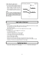
Page 23: ...A B set 1 Apply silicone rubber THREEBOND 1211 to the specified portions of housing A diagonally shaded areas as shown in Fig 9 before mounting the parts to housing A 2 After application of silicone rubber THREEBOND 1211 to housing A mount the Strap Black 43 Apply silicone rubber THREEBOND 1211 to housing B in the same manner 3 Tighten the eight Tapping Screws W Flange D4 x 20 Black 26 Wipe off si...

Page 24: ...ks of Ring Gear E 21 and Idle Gear Set 2 pcs 19 gear tooth flanks of the Hammer Case 1 and the Final Gear 2 Two Steel Balls D3 5 3 Sliding section between anvil A of the Final Gear 2 and Guide Sleeve D 6 MOLUB ALLOY 777 1 6 mm diameter hole of Anvil B 10 and the involute spline Two Steel Balls D4 76 17 Cam groove oil groove and claw of Hammer A 11 Cam groove and sliding section of the Spindle 18 3...

Page 25: ...lion direction of the push on side of the pushing button When the pusing button is turned to R side the rotation direction of anvil A should be clockwise as viewed from behind No load current 2 0 1 A DC 15 8 V equivalent to the voltage of a fully charged battery 2 Precautions in disassembly and reassembly of battery charger Refer to the Technical Data and Service Manual for precautions in disassem...

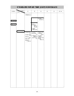
Page 26: ...ide Sleeve D Guide Spring C Hammer Case Final Gear Hammer Case Set Motor DC Speed Control Switch Trigger Paddle Lever Anvil B Ring Gear E Ball Bearing 6901VV Inner Cover D Housing A B Set Hammer A Hammer Spring Steel Ball Spindle Idle Gear Set Needle Roller A STANDARD REPAIR TIME UNIT SCHEDULES ...

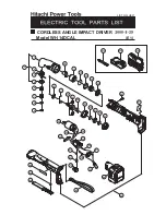
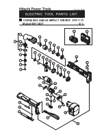
Page 27: ...Model WH 14DCAL CORDLESS ANGLE IMPACT DRIVER LIST NO H821 E1 501 502 26 17 14 15 28 34 35 36 39 29 30 38 37 44 45 18 19 20 21 22 23 24 25 31 32 33 40 42 41 43 503 27 10 11 12 13 1 2 4 6 7 16 3 8 9 5 ...

Page 28: ... 610 RING GEAR E 1 22 319 911 WASHER E 1 23 690 1VV BALL BEARING 6901VVCMPS2L 1 24 329 518 FELT 1 25 329 657 INNER COVER D 1 26 301 653 TAPPING SCREW W FLANGE D4X20 BLACK 8 27 NAME PLATE 1 28 329 669 MOTOR 1 29 329 671 INTERNAL WIRE BLACK 57L 1 30 329 656 PUSHING BUTTON 1 31 330 620 BUSHING S 1 32 330 621 SPRING S 1 33 330 622 TRIGGER 1 34 329 670 INTERNAL WIRE RED 36L 1 35 329 668 DC SPEED CONTRO...

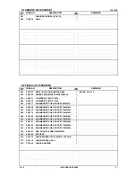
Page 29: ...85 329 NON MAGNETIC HEX SOCKET 10MM 65L 1 607 996 178 NON MAGNETIC HEX SOCKET 12MM 65L 1 608 996 179 NON MAGNETIC HEX SOCKET 13MM 65L 1 609 996 180 NON MAGNETIC HEX SOCKET 14MM 65L 1 610 996 185 NON MAGNETIC HEX SOCKET 15MM 65L 1 611 996 181 NON MAGNETIC HEX SOCKET 16MM 65L 1 612 996 182 NON MAGNETIC HEX SOCKET 17MM 65L 1 613 996 186 NON MAGNETIC HEX SOCKET 19MM 65L 1 614 996 197 HEX SOCKET LONG 2...

Page 30: ...WH 14DCAL DESCRIPTION REMARKS 4 Printed in Japan 8 08 080829N ALTERNATIVE PARTS NO USED CODE NO ITEM NO ...

Page 31: ...Model WH 14DY CORDLESS ANGLE IMPACT DRIVER LIST NO H822 E1 501 502 26 28 34 35 36 39 29 30 38 37 44 45 31 32 33 40 42 41 43 27 6 7 8 9 10 11 12 13 14 15 16 17 18 19 20 21 22 23 24 25 1 2 4 3 5 ...

Page 32: ...329 612 NEEDLE ROLLER A 2 21 329 610 RING GEAR E 1 22 319 911 WASHER E 1 23 690 1VV BALL BEARING 6901VVCMPS2L 1 24 329 518 FELT 1 25 329 657 INNER COVER D 1 26 301 653 TAPPING SCREW W FLANGE D4X20 BLACK 8 27 NAME PLATE 1 28 329 669 MOTOR 1 29 329 671 INTERNAL WIRE BLACK 57L 1 30 329 656 PUSHING BUTTON 1 31 330 620 BUSHING S 1 32 330 621 SPRING S 1 33 330 622 TRIGGER 1 34 329 670 INTERNAL WIRE RED ...

Page 33: ...CKET 10MM 65L 1 607 996 178 NON MAGNETIC HEX SOCKET 12MM 65L 1 608 996 179 NON MAGNETIC HEX SOCKET 13MM 65L 1 609 996 180 NON MAGNETIC HEX SOCKET 14MM 65L 1 610 996 185 NON MAGNETIC HEX SOCKET 15MM 65L 1 611 996 181 NON MAGNETIC HEX SOCKET 16MM 65L 1 612 996 182 NON MAGNETIC HEX SOCKET 17MM 65L 1 613 996 186 NON MAGNETIC HEX SOCKET 19MM 65L 1 614 996 197 HEX SOCKET LONG 21MMX166L 1 615 996 184 BIT...

Page 34: ...WH 14DY DESCRIPTION REMARKS 4 Printed in Japan 8 08 080829N ALTERNATIVE PARTS NO USED CODE NO ITEM NO ...

Reviews: