background image

30

Digital Display Error and Alarm Indications (Default function)

Troubleshooting (continued)

̲

̲

̲

̲̲

̲̲̲

̲

Digital Display

Display

Error/Alarm Description

Corrective Action

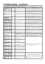
A.THI

High  ambient  temperature 
alarm

Verify that the ambient temperature is below 104

°

F  and  reset  the  air  compressor.  If  the  error  re-

occurs and the ambient temperature is below 104
° F, contact the local Hitachi distributor.

A.nnT

Maintenance alarm

This  alarm  is  displayed  when  the  total  operating 
hours  exceeds  2,500  hours.  Carry  out  inspection 
and maintenance of the air compressor.

Scroll  head  maintenance 

alarm

This  alarm  is  displayed  when  the  total  operating 
hours  exceeds  9,500  hours  (145PSIG  Model 
:   4 , 5 0 0   h o u r s ) .   C a r r y   o u t   i n s p e c t i o n   a n d 
maintenance of the scroll head.

A.OH

Overhaul alarm

This  alarm  is  displayed  when  the  total  operating 
hours exceeds between 19,000 to 19,500 hours 
(145PSIG  Model  :  between  9,000  to  9,500 
hours). Carry out overhaul of the Scroll Head.

E.CPU

Microcomputer error

Turn  off  the  main  power  supply  to  reset  the  air 
compressor  and  turn  the  power  back  on.  If  the 
error  re-occurs,  replace  the Printed  Circuit  Board. 
(Contact the local Hitachi distributor.)

E.Pr.H

Air compressor high pressure 
error

The  Electromagnetic  Contactor,  Printed  Circuit 
Board,  Pressure  Sensor  or  another  electrical 
component  has  failed.  Contact  the  local  Hitachi 
distributor.

E.Pr.S

Pressure sensor error

Tighten  the  pressure  sensor  wire  and  reset  the 
air  compressor.  If  the  error  re-occurs,  replace  the 
pressure  sensor  (Please  contact  the  local  Hitachi 
distributor).

E.Pr.E

Air compressor high pressure 
emergency stop error

The  Printed  Circuit  Board  has  failed.  Contact  the 
local  Hitachi  distributor  to  replace  the  Printed 
Circuit Board.

E.rE

Phase reversal error

Change two of the three incoming power cables.

Damage  to  reversal  phase 
wiring

Confirm that there is no disconnection or damage 
to the phase reversal wiring. If the error re-occurs, 
contact the local Hitachi distributor.

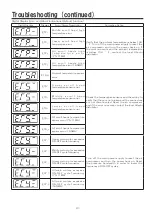
  E.Co.

Upper  main  motor  thermal 
overload error

Please  contact  the  local  Hitachi  distributor  to 
eliminate  the  probable  cause  and  reset  the  main 
motor thermal overload error.

  E.Co.

Middle  main  motor  thermal 
overload error

  E.Co.

Lower  main  motor  thermal 
overload error

  E.Co.

A l l   m a i n   m o t o r s   t h e r m a l 
overload error (7.5/11M6)

  E.Co.

A l l   m a i n   m o t o r s   t h e r m a l 
overload error (16.5M6)

E.TP.A

High  ambient  temperature 
error

Verify that the ambient temperature is below 104

°

F. Turn off the main power supply to reset the 

air  compressor  and  turn  the  power  back  on.  If 
the  error  re-occurs  and  the  ambient  temperature 
is  below  104

° F,  contact  the  local  Hitachi 

distributor.

  E.TP.

U p p e r   s c r o l l   h e a d   h i g h 
temperature error

Summary of Contents for SRL Series

Page 1: ...oll Air Compressor Please read this instruction manual carefully for installation maintenance and inspection guidelines of the HITACHI Scroll Air Compressor After reading this instruction manual please keep it on hand for future reference Pressure Units Clarification Pressure is indicated in units of psig in this Instruction Manual Please review the table below for the conversion of psig units to ...

Page 2: ...tion Model and Serial Number Vital information regarding the status of the air compressor for example alarm information in as much detail as possible Do not reprint and or reproduce any section of this instruction manual without permission from Hitachi Safety Precautions Improper use of the Oilfree Scroll Air Compressor may result in an accident or injury Thoroughly read the instruction manual bef...

Page 3: ...s other than air may lead to damage of the air compressor SRL air compressors are not designed intended or approved for breathing air applications Hitachi does not approve specialized equipment for breathing air applications and assumes no responsiblity or liability for compressors used for breathing air services If the scroll air compressor is used for any important production equipment it is hig...

Page 4: ...not operate beyond the scheduled period Failure to adhere to this precaution may cause damage to the air compressor and or accidents For more details contact the local Hitachi distributor 145PSIG Model Contact the local Hitachi distributor for the completion of the maintenance required every 5 000 hours or every 2 years of standard use The maintenance has to be completed in this period or earlier ...

Page 5: ...ration Maintenance and Inspection Troubleshooting Parts List Wiring Diagram Standard Specifications Aftermarket Ordering Procedure 2 4 4 4 5 7 8 12 12 14 19 20 21 29 33 34 36 37 Safety Precautions continued If the air compressor has not run in over one 1 month carry out the long term storage operation prior to restarting the air compressor See page 28 Failure to adhere to this precaution may cause...

Page 6: ...compressor Compressed Air Discharge Pipe Power Cable Inlet Control Panel Locks for door enclosure with Keys Front Door Emergency Stop Switch SRL 7 5M6LL ML LH MH SRL 11M6LL ML LH MH SRL 16 5M6LL ML LH MH Make sure that front door is closed during the operation of the air compressor Air Exhaust Air Intake Intake air and cooling air is supplied to the air compressor Compressed Air Discharge Pipe Pow...

Page 7: ...ose Intake Air Filter 10HP 7 7kW 3 locations 15HP 11kW 4 locations Transport Fixture 2 locations Secondary Cooler Main Power Supply Terminal Block Electromagnetic Contactor Check Valve Scroll Head Air Release Valve Power Supply Panel Electric Main Motor Rubber Vibration Isolators V Belt Primary Cooler Ventilating Fan Safety Relief Valve Rubber Hose Intake Air Filter 6 locations Transport Fixture 3...

Page 8: ...ompressor specifications Warning Label Read the Warning Label before use Do not use an air compressor with a power supply differing from the specified power requirement Incorrect power supply may cause fire and or abnormal vibration CAUTION 2 Transporting the Air Compressor Transporting the Air Compressor Removing the Transport Fixtures Moving with a Forklift Place a buffer plate in between the ai...

Page 9: ...may cause a reduction in the life of air compressor components Secure enough space for wiring and piping Ventilation and Exhaust Space Secure enough space for proper ventilation Absence of intake space causes the suction resistance to increase resulting in temperature rise in the package which may cause a reduction in the life of air compressor components Maintenance Space for Right Rear Sides If ...

Page 10: ...e Oilfree Scroll Air Compressor as it may cause damage to the air compressor Do not install the air compressor in an area above the ground as the air compressor and or parts of the air compressor may fall WARNING Do not install the air compressor on ground with insufficient weight load Do not operate the air compressor attached to a pallet or packaging table Do not install on any type of rubber ot...

Page 11: ...rs to the compressed air discharge as they may damage the discharge line of the air compressor If a remote vertical air receiver is installed it is recommended to attach the air receiver to the ground with foundation bolts WARNING 4 Piping the Air Compressor Safety Relief Valve If a stop valve is installed in the middle of the compressed air piping install a safety relief valve between the air com...

Page 12: ...per the local and national electric codes Improper wiring may lead to excessive voltage drops Do not use a generator CAUTION 5 Wiring the Air Compressor Connecting the Main Power Model Power Wiring Capacity Minimum Wire Thickness mm AWG Minimum Ground Line Wire Thickness mm AWG Circuit Breaker Capacity A Fuse Capacity A SRL 7 5M6LL SRL 7 5M6LH 208 230V 3 Phase 60 Hertz 3 9 AWG8 3 9 AWG8 75 75 SRL ...

Page 13: ...o fix the problem turn off the main power and reconnect the power after switching two of three wires of the main power If nothing has changed after reconnecting please refer to P 29 8 If the air compressor is rotating correctly the cooling air flows as shown in the figure to the right 9 Make sure to turn off the main power supply before carrying out any wire connections Firmly tighten the screws c...

Page 14: ...ange over signal will occur A character r Remote mode is displayed on the left most position of the digital display When remote control is to be used the remote operation change over signal must occur before activating the remote operation command signal The input signal is approximately 5VDC 10mA Use a switch or a relay contact with the minimum applicable load of this value Installation continued...

Page 15: ... No Terminal Description Content How to use Operation Signal This signal is outputted when the operation is ON The output is a non voltage signal The load connected should be 250VAC 30VDC 5A or less and should use an auxiliary relay of small load Error Signal This signal is outputted when the errors occur and the air compressor cannot be restarted Alarm Signal This signal is outputted when an alar...

Page 16: ...seconds Maintenance Alarm Light Red Lights up to inform operating personnel that maintenance is required based on hours of operation Start and Stop Switch Pressing these switches starts and stops the air compressor respectively Compressor Operation Light Green Lights up during compressor operation If nothing displays in the digital display even with power on either the emergency stop switch is ope...

Page 17: ...as a guide for scheduling maintenance for the air intake filter V belt and other normal inspection maintenance items Press Screen Shift Switch Again Within Three Seconds Pressing the Screen Shift Switch again within three seconds will show the total operating hours of the Scroll Head for three seconds Note Displays the total operating hours of the scroll head only Use these displays as a guide for...

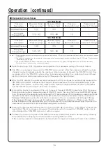
Page 18: ...matically to keep the delivery pressure at around the necessary pressure recovery pressure This operation allows the compressor to save energy by avoiding useless operation of compressor heads 2 Pressure Switch Control Mode The operation of SRL compressor heads is controlled by Pressure Switch Control Mode The operation of all SRL compressor heads are stopped simultaneously when the unit stops ope...

Page 19: ...tart Pressure psig 110 115 EX 122PSIG Model Digital Display Steps 5 6 Steps 2 3 4 Steps 2 4 Steps Digital display 1 Verify that the pressure is indicated on the digital display 2 Press the stop switch and then press the start switch and hold both buttons for 5 seconds to change the indication on the digital display to PC 3 To change the maximum stop pressure press the start switch The indication o...

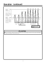
Page 20: ...e operation of the air compressor will stop to protect the compressor head electric motors and electromagnetic contactor Pressing the Stop switch will reset the unit from the ON OFF cycle error and allow it to restart the operation of the air compressor However if the situation which caused the ON OFF cycle error is not eliminated the ON OFF cycle error will occur again To lower the amount of cycl...

Page 21: ...TART Standard Maximum Pressure 122psig 145psig Standard Recovery Pressure 110psig 115psig T h e m a x i m u m Stop Pressure setting has been changed on the control panel of the air compressor The recovery Start Pressure setting has been changed o n t h e c o n t r o l panel of the air compressor As the protection device extends the ON OFF cycle the discharge pressure may exceed the setting maximum...

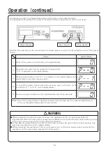
Page 22: ...h there is not a digital display When restarting the operation of the air compressor turn on the main power supply and verify the operation control mode before pressing the Start switch WARNING Digital Display Start Switch Stop Switch Steps Digital Display 1 Verify if the pressure is indicated on the digital display 2 Press the stop switch continuously for three seconds P 0 is indicated on the dig...

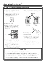
Page 23: ...ower supply to the air compressor Open the discharge stop valve to lower the pressure and verify that the air compressor restarts at the load pressure setting Close the stop valve on the air receiver and verify that the operation of the air compressor stops when the pressure reaches maximum pressure under pressure switch control mode During operation of Multi Drive control mode the SRL compressor ...

Page 24: ... 0 psig even if the air receiver has been de pressurized Ventilate to lower the ambient temperature In the case of a power failure and or electric storm ensure that the main power supply has been turned off Pay attention that residual pressure may exist since there is no digital display Operation continued 4 Daily Operation Do not operate a damaged and or improperly activated air compressor Do not...

Page 25: ...ensor Inspect operation and pressure display confirm Replace the sensor if there is any damage Check Valve Inspect for leaks or replace Ventilating Fan Inspect or replace the ventilating fan Refer to page 26 Bolts Nuts Screws Inspect and tighten any loose items Refer to page 26 Intake Air Filter Replace a dirty or clogged filter Refer to page 26 Sirocco Fan Scroll Fin Clean the dirt off these comp...

Page 26: ...h bearings Scroll Head Replace the scroll head Rubber Hose Inspect for leaks Replace the rubber hose if there is any damage V Belts Inspect adjust and or replace a loose or damage v belt Refer to page 27 Electromagnetic Contactor Inspect or replace Rubber Vibration Isolator Pads Inspect for any damage and or hardness Replace the pads if there is any damage Electric Main Motor Inspect for any damag...

Page 27: ...tinuously without performing maintenance and inspection may result in serious accidents and or damage to the air compressor Turn off the main power supply and vent the pressurized air in the air compressor prior to performing any maintenance or inspections This will prevent electric shock and or personal injury The maintenance and inspection schedule is not guaranteed and is designed for normal op...

Page 28: ...ut Maintenance Alarm Reset Alarm Output Maintenance 9 500Hrs 9 500 Hrs A Hrs Overhaul Alarm Output 19 000 A Hrs A 500Hrs Alarm Reset 9 500 Hrs 9 500 Hrs Alarm Reset Alarm Output Maintenance B Hrs Overhaul Alarm Output 19 500Hrs B 500Hrs Scroll Head Maintenance and Overhaul 145PSIG Alarm Output Overhaul Alarm Reset Alarm Output Maintenance 4 500Hrs 4 500 Hrs A Hrs Overhaul Alarm Output 9 000 A Hrs ...

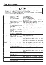
Page 29: ...and screws Any moving components have come in contact with other components Contact the local Hitachi distributor Scroll head and or electric motor have excessive viblation and or sound The installation area cannot handle the weight load of the air compressor Relocate the air compressor to an area that can sufficiently handle the weight load or strengthen the existing installation area The rubber ...

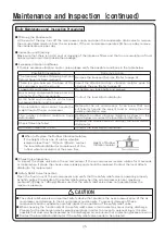
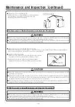
Page 30: ...he inspection and cleaning WARNING 500 Hours and or 2 Months Maintenance and Inspection Procedures Wear the proper eye or body protection when servicing the air compressor to prevent inhaling harmful particles such as dust Replace the intake air filter and filter spacer if the intake air filter is considerably dirty and or clogged This will prevent the intake air filter from causing compressed air...

Page 31: ...or may occur If the scroll does not rotate smoothly and or a large amount of grease leaks from the bearing contact the local Hitachi distributor immediately 3 Check valve The seating section and valve body of the check valve will wear over time causing a malfunction to the check valve and damage to the air compressor 4 Ventilating Fan Electromagnetic Contactor and V belt Maintenance and Inspection...

Page 32: ...condensate in the air receiver 3 Storage Location Store the air compressor in the one of the following areas 1 Storage area with minimal moisture 2 Storage area that is not subject to contaminants and or dust 20 000 Hours and or 8 Years Maintenance and Inspection Procedures 122PSIG Model Long Term Storage SRL Air Compressor Out of Service for Over One Month 122PSIG Model Eight 8 years or 20 000 ho...

Page 33: ...heck valve Please contact the local Hitachi distributor High discharge pressure Printed circuit board failure Replace the printed circuit board Please contact the local Hitachi distributor Electromagnetic contactor failure Replace the electromagnetic contactor Please contact the local Hitachi distributor Excessive noise is generated Improper installation Install the air compressor on level ground ...

Page 34: ...ed Circuit Board Pressure Sensor or another electrical component has failed Contact the local Hitachi distributor E Pr S Pressure sensor error Tighten the pressure sensor wire and reset the air compressor If the error re occurs replace the pressure sensor Please contact the local Hitachi distributor E Pr E Air compressor high pressure emergency stop error The Printed Circuit Board has failed Conta...

Page 35: ...wiring to verify that they are not broken and the connectors are not disconnected Reset the air compressor and if the error re occurs contact the local Hitachi distributor E TS U p p e r s c r o l l h e a d temperature sensor error E TS M i d d l e s c r o l l h e a d temperature sensor error E TS L o w e r s c r o l l h e a d temperature sensor error E TS All scroll heads temperature sensor error...

Page 36: ...elow the set value this alarm is displayed while the air compressor continues to operate E nT U p p e r s c r o l l h e a d maintenance shutdown If the total operating hours exceeds the required maintenance interval the air compressor ceases operation and this alarm is displayed E nT M i d d l e s c r o l l h e a d maintenance shutdown E nT L o w e r s c r o l l h e a d maintenance shutdown E nT A...

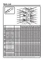
Page 37: ...or 760201 1 1 1 1 2 2 2 2 3 3 3 3 12 Fuse for UL Power Supply Panel 742352 2 2 2 2 2 2 2 2 2 2 2 2 13 Relay 760207 6 6 6 6 6 6 6 6 7 7 7 7 14 Circuit breaker No 1 for AC208 230V 760198 1 1 1 1 1 1 Circuit breaker No 1 for AC460V 760199 1 1 1 1 1 1 15 Circuit breaker No 2 742351 1 1 1 1 1 1 1 1 1 1 1 1 16 Motor Breaker for AC208 230V 760202 1 1 760203 1 1 2 2 3 3 Motor Breaker for AC460V 760204 1 1...

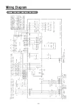
Page 38: ...Wiring Diagram 34 SRL 7 5M6LL ML LH MH SRL 11M6LL ML LH MH ...

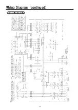
Page 39: ...Wiring Diagram continued 35 SRL 16 5M6LL ML LH MH ...

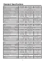
Page 40: ... 6 1 830 Power Requirements V Φ Hz AC 460 3 ph 60 Main Electric Motor Amp Draw A 4 1 9 3 9 3 2 9 3 3 Total Package Amp Draw A 14 4 19 3 28 8 Scroll Head Revolutions min 1 3 415 2 2kW 3 340 5 5kW 3 340 3 340 Compressed Air Discharge Connection Size 3 4 NPT Male 1 NPT Male Inside Air Receiver Without External air receiver should exceed 80 Gallons Package Dimensions L W H Inch mm 38 58 27 95 52 95 98...

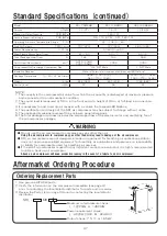
Page 41: ...verted to an atmospheric condition 2 The sound level is measured at 59 in in the front and at a height of 39 in at full load in an anechoic room 3 It is necessary to add a remote air receiver with a volume that exceeds 80 Gallons 4 The specification and design of the SRL air compressor may be subject to change without notice 5 The package dimensions represent the enclosure panel dimensions 6 The t...

Page 42: ...Log Book 38 ...

Page 43: ...Log Book 39 ...

Page 44: ...p Date MM DD YYYY Local Hitachi Distributor Name Tel Inspection date Maintenance service date of completion MM DD YYYY Next Inspection and service schedule date Maintenance and inspection results Initials of employee Intake air filter Check valve Rubber hose Ventilating fan Other Hitachi Industrial Equipment Systems Co Ltd M L e c n a n e t n i a k o o b g o Maintenance and Inspection Logbook Tabl...

Reviews: