3
Chapter 2
Name of parts and contents
2.1
Name of parts and contents
Tab. 2
Name of parts and contents
No.
Name of parts
Color
Contents
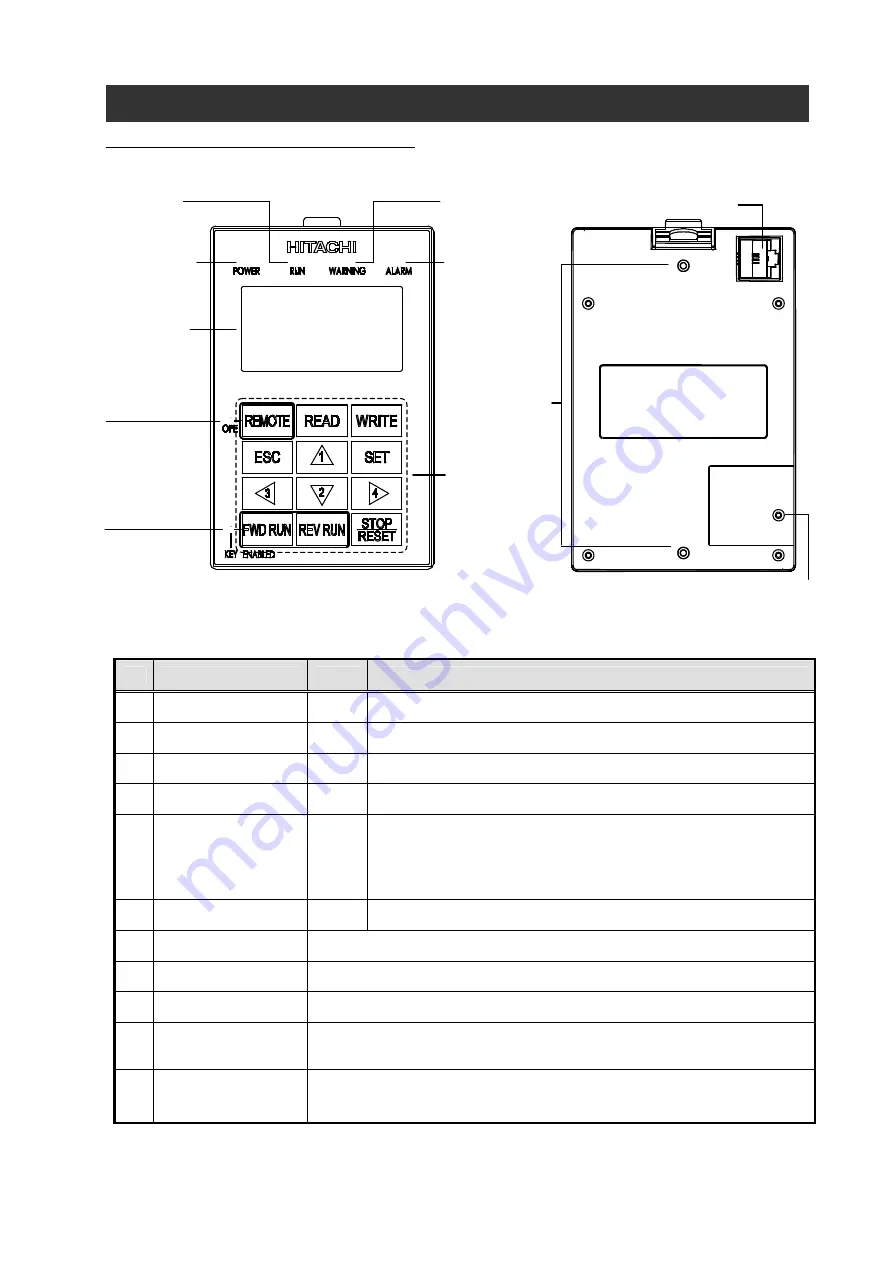
1
POWER LED
Green Light on when power is supplied to the operator.
2
RUN LED
Green Light on when the Inverter is running.
3
WARNING LED
Red
Light on when parameter setting is incorrect.
4
ALARM LED
Red
Light on when the Inverter trips.
5 OPE
LED
Green
Light on when the REMOTE key makes the compulsion
operation function effective. It doesn't light when the compulsion
operation function is effective by input terminal OPE. (Press the
key more than 2s)
6
KEY ENABLED LED Green Light on only when operation command is set in operator.
7
LCD display
Refer to section 2.4 for details.
8
Operation key
Refer to Tab. 3 for details.
9
Connector
It can be connected to the main body of the Inverter via a cable (optional).
10 Hole for installation
It is the hole for installation on the control panel. Please fix with M3 screw.
11
Battery exchange
cover
fixation screw
Please unscrew this one and detach the cover for replacing the battery.
(NOTE1) (Refer to section 9.3 for more details)
(NOTE1) Because the first battery is for operation check, it may become the life immediately.
4 ALARM LED
3 WARNING LED
2 RUN LED
1 POWER LED
7 LCD display
8 Operation key
5 REMOTE LED
6 KEY ENABLED
LED
9 Connector (RJ45)
10 Hole for
installation
(
M3 Depth3.5mm
)
11 Battery exchange cover
fixation screw
M2
×
8mm
Chapter 2
Name of parts and functions of WOP
REMOTE OPERATOR
○
○
○
○
○
○


