


– 124 –
29
17
Drive signal at point (C)
Drive signal at point (D)
•
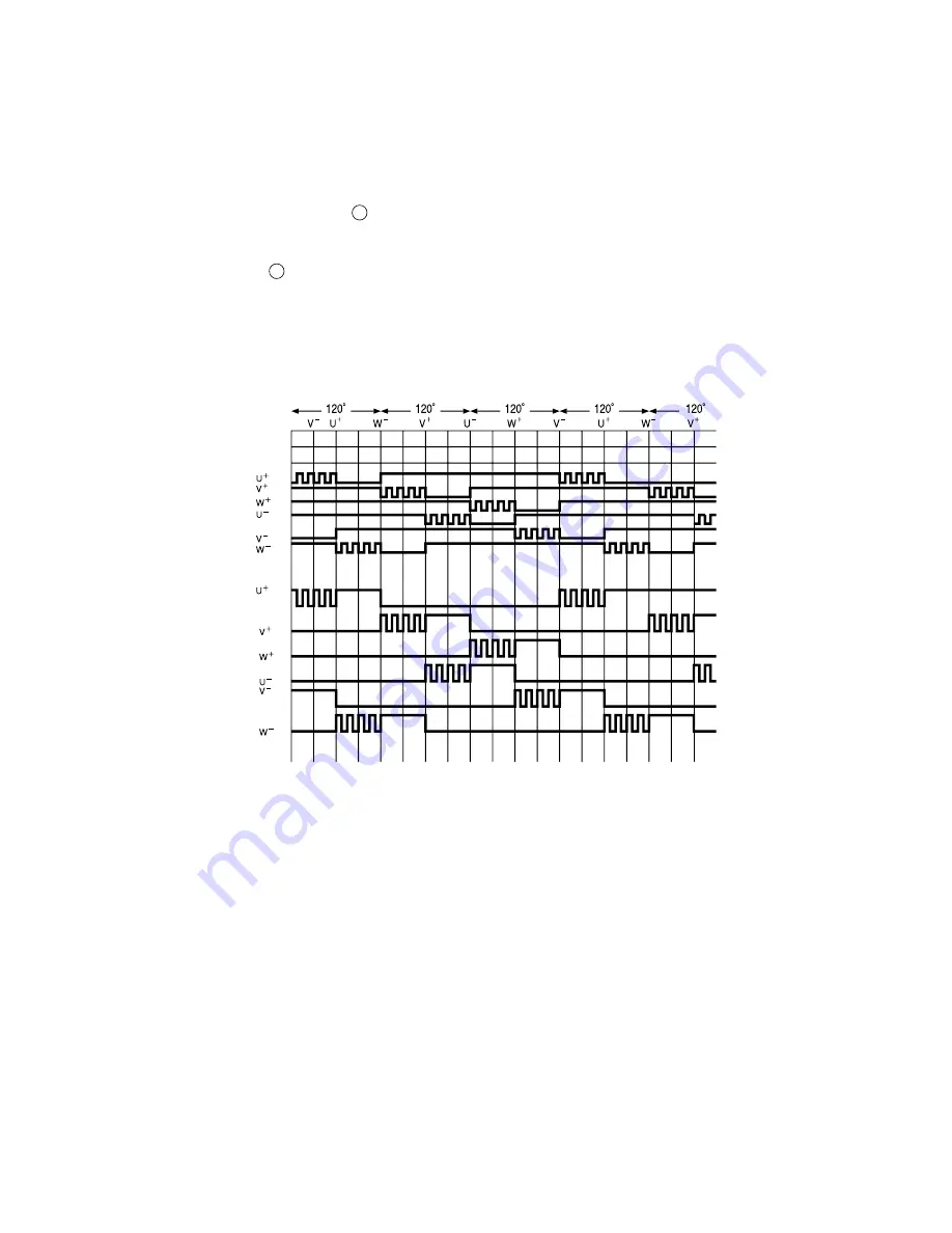
IPM drive circuit
The inverter driving device (IGBT) and the drive circuit are built in the IPM. The IPM receives the
signal from the microcomputer and convert it to 0 – 15 V signal to drive the IGBT.
When the unit operates at low speed, a chopper signal is emitted from the microcomputer as shown
in Fig. 4-6. (0 to 5 V)
The signal is converted to 0 – 15 V at inside the IPM and transmitted to the gate of the transistor
(IGBT) in each phase to drive the IGBT.
When abnormal peak current was detected while the inverter is driving, the IPM outputs the Fail
signal immediately from the pin
and forces the lower arm transistor to shut off at the same time.
In this step, the Q501 is turned on and the input signal of the upper arm is also shut off through the
D501 and D502, so that all signals to the IGBT are shut off. This signal is also distributed to
microcomputer (pin ) as a Lo signal to stop the drive signal and blink the self diagnosis lamp as two
time.
When the peak current is detected, the IPM keeps the lower arm off for about 4ms. and the drive
signal into stand-by state. 3 minutes after this state, the microcomputer outputs the drive signal and
restarts the operation.
5V
0V
15V
0V
Fig. 4-6
Summary of Contents for RAC-25FX8
Page 44: ... 49 MODEL RAC 25FX8 RAC 35FX8 SELF CHECK SELF MODE FORCECOOLING RED RED RED ...
Page 48: ...BASIC MODE MODEL RAF 25FX8 RAF 35FX8 57 button 63 67 67 71 75 67 ...
Page 148: ... 166 SELF DIAGNOSIS LIGHTING MODE MODEL RAC 25FX8 RAC 35FX8 ...
Page 191: ...TC NO 0780EF RAF 25FX8 RAC 25FX8 RAF 35FX8 RAC 35FX8 Printed in Japan HRT ...


