--- 29 ---
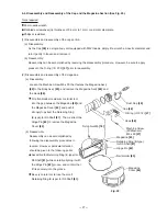
O-ring (P-4)
[36]
Fig. 22
Nose
[69]
(3) Disassembly and reassembly of the Feeder
[30]
, Feed Piston
[72]
and related parts (See Fig. 21.)
(a) Disassembly
Remove the Magazine Ass'y
[85]
from the Body Ass'y
[20]
by following the procedures described in item
9-4-(2).
After removing the Retaining Ring for D28 Hole
[77]
, the Feed Piston Cover
[75]
, Bumper
[74]
and Feed
Spring
[73]
can be taken off.
After extracting Roll Pin D4 x 14
[26]
, the Feed Piston
[72]
and the Feeder Arm
[28]
can be taken off.
After extracting the Needle Roller
[27]
, the Feeder Arm
[28]
and Feeder
[30]
can be separated.
(b) Reassembly
Reassembly can be accomplished by following the disassembly procedures in reverse. However, particular
attention should be given to the following points.
As the operation of the Feed Piston
[72]
becomes poor if the air passages in the tail cover and the feed
piston chamber become clogged with pieces of the Piston Bumper
[17]
or other foreign matter, carefully
clean them prior to reassembly.
Prior to reassembly, apply grease to the O-ring (P-9)
[70]
and the O-ring (1AP-20)
[71]
.
As shown in Fig. 23, position the Feed Piston
[72]
and the O-ring (1AP-20)
[71]
on the right side, and
apply grease to the groove section.
Apply grease to the O-ring sliding portions of the Feed Piston
[72]
and the Nose
[69]
, and to the O-ring.
However, as excessive grease will cause poor movement of the Feed Piston
[72]
, be very careful not to
apply too much grease.
Ensure that the Retaining Ring for D28 Hole
[77]
is properly fitted into the groove of the Nose
[69]
.
When driving in the Roll Pin D4 x 14
[26]
, ensure it is inserted so that its split end is on the magazine
side, as shown in Fig. 24.
(2) Disassembly and reassembly of the Vertical Guide
[35]
and related parts (See Fig. 22.)
(a) Disassembly
Using a flat-blade screwdriver, remove the O-ring (P-4)
[36]
and extract the Guide Shaft
[33]
.
The Vertical Guide
[35]
and Spring
[32]
can then be removed.
(b) Reassembly can be accomplished by
following the disassembly procedures in reverse.
However, particular attention should be given to
the following points.
Ensure that the Guide Shaft
[33]
is assembled
so that the O-ring (P-4)
[36]
is on the side
toward you (the nail guide side), as illustrated in
Fig. 22.
Confirm that the Spring
[32]
is properly fitted
onto the protruding portions of the Nose
[69]
and the Vertical Guide
[35]
.
Vertical Guide
[35]
Spring
[32]
Protruding portion
Protruding
portion
Guide
Shaft
[33]
Summary of Contents for NV 50AG2
Page 39: ......


