


--- 25 ---
Grip Tape
[45]
Steel Ball D3.97
[51]
Spring (C)
[52]
Change Knob (B)
[55]
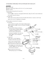
Fig. 15 Disassembly and reassembly of the control valve section
Body Ass'y
[20]
Rod
Fig. 16
Tape
[46]
Valve Bushing (B)
[59]
O-Ring (S-18)
[60]
O-Ring (I.D 8.8)
[61]
Valve Piston (B)
[63]
O-Ring (I.D 11)
[64]
Plunger Spring
[65]
Plunger (A)
[66]
O-Ring (I.D 1.8)
[67]
Valve Bushing (A)
[68]
Head Valve
O-Ring (I.D 16.8)
[58]
Roll Pin D3 x 18
[53]
Trigger (A)
[22]
Retaining Ring (E-Type)
for D6 Shaft
[19]
Roll Pin
D3 x 25
[54]
Pushing Lever
Guide
[23]
Fig. 17
Valve Bushing (B)
[59]
Hole
Steel wire
(b) Reassembly
Reassembly can be accomplished by following the disassembly procedures in reverse. However, particular
attention should be given to the following points.
Be very careful not to allow any foreign matter to get into the control valve section.
Liberally apply grease to Plunger (A)
[66]
, O-ring (I.D 1.8)
[67]
, Valve Piston (B)
[63]
, O-ring (I.D 8.8)
[61]
and O-ring (S-4)
[62]
.
As shown in the following illustrations, assemble Valve Bushing (A)
[68]
so that its roll pin groove is aligned
with the matching roll pin hole in the Body Ass'y
[20]
, insert the 3 mm dia. roll pin remover, and after
ensuring that it passes smoothly through the roll pin hole, drive in the Roll Pin D3 x 18
[53]
. If the Roll Pin
D3 x 18
[53]
is forcibly driven in when the roll pin grooves of Valve Bushing (A)
[68]
and the Body Ass'y
[20]
are not properly aligned, the outer circumference portion of Valve Bushing (A)
[68]
will be damaged, and
further disassembly and reassembly will not be possible.
O-Ring (S-4)
[62]
Summary of Contents for NV 50AG2
Page 39: ......