4 OPERATION
4-11
④
The PCs edition items’ initial settings displayed are as follows:
Number of data words to be transferred at a time: None (for receive only)
Hold/Clear: Clear (This PCs edition item is used to determine whether to hold or clear
the contents of the G-register area in the event of a reception timeout
detected. For details, see “(4) Reception timeout” in “5.1 Transfer
Cycle.”)
If you want to change these initial settings, do the following:
• Changing the number of data words to be transferred at a time
The number of data words to be transferred at a time (“CPU link transfer area”) can be
changed by performing the following steps: 1) Click the “Receive only” check box to
deselect it and 2) specify the starting address and ending address of the transfer area in
the left edit box and the right edit box, respectively, within the transfer-area setup field.
The transfer of data words is performed using the G-register area (G000 through
GFFF), so the starting and ending addresses need to be specified in the range /000 to
/FFF. The maximum number of data words (data points) that can be transferred at one
time is 1024 (/400). For more information on the number of data words to be
transferred at a time and their range, see “5.1 Transfer Cycle.,”
• Changing the “Clear” setting to “Hold”
To change the “Clear” setting to “Hold”, just click the [Hold] radio button in the
window.
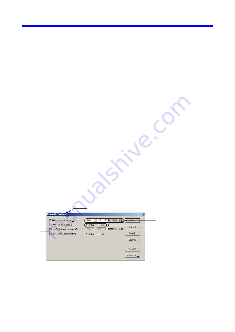
Figure 4-11 shows an example in which the starting and ending addresses are set to /100
and /1FF, respectively, with “Clear” selected.
Figure 4-11 [[Online] PCs edition] Window (Updated)
As shown above, an asterisk (“*”) will be displayed to the right of the [[Online] PCs
edition] window’s title when you add a change to the existing parameter values in the
window.
Data word count setting
Clear/Hold setting
Settings for a CPU link module to be used as the submodule
Settings for a CPU link module to be used as the main module
An asterisk (“*”) displayed to the right of the window title
Summary of Contents for LQE550
Page 1: ......
Page 2: ......
Page 17: ...This Page Intentionally Left Blank ...
Page 19: ...This Page Intentionally Left Blank ...
Page 28: ...1 SPECIFICATIONS ...
Page 34: ...2 NAMES AND FUNCTIONS OF EACH PART ...
Page 38: ...3 MOUNTING AND WIRING ...
Page 46: ...4 OPERATION ...
Page 75: ...4 OPERATION 4 30 Figure 4 33 An Example of a CPU Link Parameters Output in CSV Format ...
Page 79: ...This Page Intentionally Left Blank ...
Page 80: ...5 PROGRAMMING ...
Page 88: ...6 MAINTENANCE ...


