background image

-1-

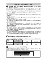
Equipped with four existing electronic co two most

advanced controls

These products are highly functional electronic disc grinders that provide added value and incorporate a
microcomputer with a new original program loaded in place of a conventional general-purpose IC, four fully
updated control features—(1) constant speed control, (2) soft-start speed control, (3) variable speed control
(on Models G 12VA, G 13VA and G 15VA), and (4) overload protection control—and two new additional
control features—(5) kickback protection control and (6) 0-voltage restart protection control.
1. Constant speed control

The constant speed control feature maintains constant rotation speed during operation to ensure highly
efficient work.

2. Soft-start speed control

The soft-start speed control feature reduces the reactive force generated at motor startup so as to lessen
the load on the operator's hands.

3. Variable speed control (G 12VA, G 13VA and G 15VA only)

The variable speed control feature selects an appropriate rotation speed for different applications to
ensure highly efficient work.

4. Overload protection control

The overload protection feature shuts off power to the motor in the event of motor overload or a
conspicuous reduction in rotation speed during operation. This feature thus reduces the risk of motor
burnout and controller failure.

5. Kickback protection control

The kickback protection feature cuts off power to the motor and stops the power tool in the event of a
sudden drop in wheel rotation speed during operation (e.g., wheel locking during cutting operation). This
feature thus lessens the load on the operator's hands.

6. 0-voltage restart protection control

The 0-voltage restart protection feature disables motor startup even with the main switch on when the
power cord is reconnected to the power outlet after being unplugged during operation or when the power
supply is recovered from power failure. This feature thus minimizes accidents due to motor restart.

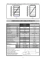
    Equipped with most powerful motor in its class

These products are equipped with a high-performance, powerful motor featuring the highest input and
output in its class to enable highly efficient work.

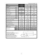
Maker

HITACHI

Model

G 12VA, G 13VA, G 13YF,

G 15VA and G 15YF

B1, B2

C1, C2, C3

Power input

1500W

1400W

1400W

Max power output

2800W

2100W

2650W

Excellent overload durability (G 13VA)

The Model G 13VA provides the highest overload durability in its class (1.2 times higher than that of B1)
thanks to an improved cooling mechanism and a high-power motor.

116

100

123

0

50

100

150

SELLING POINT DESCRIPTIONS

G 13VA

B1

C2

Practical test data: Comparison of torque at 200-K rise in stator coil temperature

Summary of Contents for G 12VA

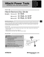
Page 1: ... 15VA G 15YF Removal of casting fins and the finishing of various types of steel bronze aluminum and various other metallic materials Grinding of welds or sections cut by a cutting torch Grinding of synthetic resins slate brick marble and other materials MARKETING OBJECTIVE APPLICATIONS SELLING POINTS NEW FEATURES Equipped with four existing electronic controls two most advanced controls 1 Constan...

Page 2: ...f company name s and model name s of our competitor s The symbol s utilized here is are as follows G 12VA Competitors Symbols Utilized Company Name Model Name C1 MAKITA 9564CV G 13VA G 13YF Competitors Symbols Utilized Company Name Model Name B1 BOSCH GWS14 125CIE GWS14 125CI C2 MAKITA 9565CV 9565C G 15VA G 15YF Competitors Symbols Utilized Company Name Model Name B2 BOSCH GWS14 150CI C3 MAKITA 95...

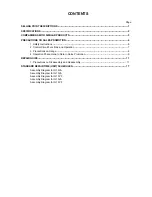
Page 3: ...ontrol Circuit Functions and Operation 7 3 Precautions on Usage 8 4 Operation Phenomena to Note in Sales Promotion 9 REPAIR GUIDE 11 1 Precautions on Disassembly and Reassembly 11 STANDARD REPAIR TIME UNIT SCHEDULES 17 Assembly Diagram for G 12VA Assembly Diagram for G 13VA Assembly Diagram for G 13YF Assembly Diagram for G 15VA Assembly Diagram for G 15YF ...

Page 4: ...rotation speed during operation This feature thus reduces the risk of motor burnout and controller failure 5 Kickback protection control The kickback protection feature cuts off power to the motor and stops the power tool in the event of a sudden drop in wheel rotation speed during operation e g wheel locking during cutting operation This feature thus lessens the load on the operator s hands 6 0 v...

Page 5: ...otor Enclosure Housing black Tail cover green Gear cover Packing gland Aluminum alloy die casting Type of switch Slide switch Net 2 0 kg 4 4 lbs Weight Gross 2 9 kg 6 4 lbs 3 0 kg 6 6 lbs 3 1 kg 6 8 lbs Type of packing Corrugated cardboard box Plastic case Standard accessories Depressed center wheel 115 mm 4 1 2 1 Side handle 1 Wrench 1 Hex wrench 1 Depressed center wheel 125 mm 5 1 Side handle 1 ...

Page 6: ...ded None Tool less wheel guard Provided Provided Anti vibration side handle 3 Provided None Weight 4 Actual weight kg 2 0 4 4 lbs 2 9 6 4 lbs 1 9 4 2 lbs 2 7 6 0 lbs L mm 297 5 11 45 64 299 0 11 25 32 Dimensions H mm 70 0 2 3 4 80 0 3 9 64 P mm 220 0 8 21 32 212 0 8 11 32 1 Depends on the market 2 Service life of carbon brushes based on continuous rated load test 3 Except for HKU HTM 4 Weight with...

Page 7: ...tection Provided Provided None Kickback protection Provided Provided None Tool less wheel guard Provided Provided Provided Anti vibration side handle 3 Provided Provided None Weight 4 Actual weight kg 2 0 4 4 lbs 3 0 6 6 lbs 1 8 4 0 lbs 3 0 6 6 lbs 1 9 4 2 lbs 2 8 6 2 lbs L mm 297 5 11 45 64 298 0 11 47 64 299 0 11 25 32 Dimensions H mm 70 0 2 3 4 70 0 2 3 4 80 0 3 9 64 P mm 220 0 8 21 32 212 0 8 ...

Page 8: ...vided Provided None Kickback protection Provided Provided None Tool less wheel guard Provided Provided Provided Anti vibration side handle 3 Provided Provided None Weight 4 Actual weight kg 2 0 4 4 lbs 3 1 6 8 lbs 1 8 4 0 lbs 3 1 6 8 lbs 1 9 4 2 lbs 2 9 6 4 lbs L mm 297 5 11 45 64 298 0 11 47 64 299 0 11 25 32 Dimensions H mm 70 0 2 3 4 70 0 2 3 4 80 0 3 9 64 P mm 220 0 8 21 32 212 0 8 21 32 212 0...

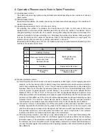
Page 9: ...nts of the Handling Instructions in order to offer appropriate guidance to customers during sales promotion activities 1 Checking the power source voltage Ensure that the power source voltage complies with the power specifications listed on the Name Plate Never operate the Models G 12VA G 13VA G 13YF G 15VA and G 15YF using a direct current DC power source The control circuit in these tools functi...

Page 10: ...variable resistor and the on or off state of the main switch The microcomputer performs the following controls based on precise trigger signal control Soft start speed control The microcomputer generates trigger signals so that the triac s conduction angle is gradually increased until motor speed reaches the reference rotation speed Constant speed control The microcomputer generates trigger signal...

Page 11: ...ely stop the spindle In such case the wheel nut may become loose and the depressed center wheel could suddenly fly off possibly causing serious injury 2 Using this product near a welding machine may cause the motor rotation speed to fluctuate Since the control circuit of this product includes a magnetic sensor to detect flux changes and a triac which may malfunction due to noise instruct the custo...

Page 12: ...otection control and automatically stop the motor This is because overload protection control detects the increased flow of current caused by excessive pressure on the tool and automatically turns off the motor to protect it against possible overload burnout The customer should be advised that the Models G 12VA G 13VA G 13YF G 15VA and G 15YF are specifically designed to perform more efficiently a...

Page 13: ... seconds later to stop the motor Instruct the customer to immediately turn off the main switch in case kickback protection control is actuated separate the tool attached to the grinder from the workpiece turn on the main switch wait until the rotation speed increases to normal speed and then resume work Also advise the customer that overload protection control will quickly reactuate even under a s...

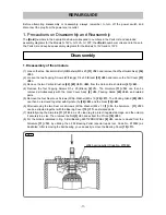
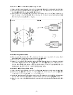
Page 14: ...pping Screws D5 x 25 Black 2 1 The Armature 11 12 can then be removed simultaneously with the Gear Cover Ass y 4 5 Packing Gland 25 26 and related parts 5 Remove the four Seal Lock Screws W Sp Washer M5 x 16 26 27 The Packing Gland 25 26 can then be removed together with Spindle A 28 29 and the Gear 19 20 6 After removing the two Seal Lock Screws W Sp Washer M4 x 10 1 3 the Armature 11 12 can be e...

Page 15: ...emoving Ball Bearing 608VVC2PS2L 17 18 3 Disassembly of the gear 1 Loosen the four Seal Lock Screws W Sp Washer M5 x 16 26 27 and then remove the Packing Gland 25 26 together with Spindle A 28 29 and the Gear 19 20 from the Gear Cover Ass y 4 5 as a single body 2 When necessary to remove the Gear 19 20 from Spindle A 28 29 it is highly recommended to use the special repair tools described below As...

Page 16: ...the Housing 39 40 3 Loosen the two Hex Hd Tapping Screws D4 x 70 13 14 and then remove the Stator 14 15 and Internal Wire 51 52 from the Housing 39 40 If the Stator 14 15 proves difficult to remove from the Housing 39 40 use an appropriate heating device to heat the Housing 39 40 to a temperature of about 60 C 140 F in order to facilitate disassembly 6 Removal of the slide switch knob 1 Loosen the...

Page 17: ...all bearing Replace Dust Seal A 16 17 with a new one without fail Press fit Ball Bearing 608VVC2PS2L 17 18 into the position shown in Fig 7 4 Apply Three Bond TB 1406 Screw Locking Agent to the following screws Two Seal Lock Screws W Sp Washer M4 x 10 1 3 that secure the Bearing Cover 10 11 in place Three Seal Lock Screws W Sp Washer M4 x 8 21 22 that secure the Bearing Cover B 22 23 in place Four...

Page 18: ...91 52 53 Terminal 60 61 Carbon Brush Holder 41 42 Side B Carbon Brush Holder 41 42 Side A Side A Side B Connect to the Carbon Brush Holder 41 42 Side A 1 2 3 4 Connect to the Carbon Brush Holder 41 42 Side B Controller 53 54 Connector 50091 52 53 Pillar Terminal 48 49 Connector 50091 52 53 Internal Wire 51 52 Gray Terminal 60 61 Cord 63 64 Switch 49 50 Blue or White White or Brown Black or Blue Bl...

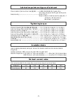
Page 19: ...t lbs Tapping Screw D3 x 10 44 45 0 74 r 0 15 N m 7 5 r 1 5 kgf cm 0 5 r 0 1 ft lbs Magnet 18 19 M6 left hand thread 1 27 r 0 29 N m 13 r 3 kgf cm 0 9 r 0 2 ft lbs Nut M8 5 13 7 r 2 0 N m 140 r 20 kgf cm 10 1 r 1 5 ft lbs Spacial Nut M6 6 5 1 r 1 0 N m 50 r 10 kgf cm 3 6 r 0 7 ft lbs Upon completing disassembly and repair measure the insulation resistance and conduct a dielectric strength test Ins...

Page 20: ... x 2 Spring x 2 Controller Snap Switch Cord Cord Armor Pinion Ball Bearing 629T12DD Bearing Cover Armature Dust Seal A Ball Bearing 608VV Gear Cover Ass y Pushing Button Lock Pin Gear Bearing Cover B Ball Bearing 6201VV Felt Packing Packing Gland Feather Key Spindle Housing Stator Slide Switch Knob Slide Bar Spring STANDARD REPAIR TIME UNIT SCHEDULES ...

Page 21: ...8㨯28 G12VA TU01672 ᒻ ޓޓޓ ฬ ޓޓޓ ዤ ޓ ᐲ 31 Rev 1 501 503 1 2 3 4 5 6 7 8 9 10 11 12 13 14 15 16 17 18 20 21 22 23 24 25 26 27 28 29 31 32 33 35 36 37 34 39 46 47 38 40 41 42 48 49 53 58 59 52 55 56 61 57 62 63 19 60 54 50 41 45 43 40 44 30 51 52 64 502 ...

Page 22: ...22 936 680 BEARING COVER B 1 23 620 1DD BALL BEARING 6201DDCMPS2L 1 24 308 546 FELT PACKING 1 25 308 545 PACKING GLAND 1 26 307 046 SEAL LOCK SCREW W SP WASHER M5 X 16 4 27 944 109 FEATHER KEY 3 X 3 X 8 1 28 994 301 SPINDLE A 1 28 994 302 SPINDLE B 1 FOR USA CAN MEX 29 311 492 LABEL 1 30 311 744 SET PIN 1 31 316 107 HEX SOCKET HD BOLT W WASHERS M5 X 20 1 32 311 491 SET PIECE B 1 33 874 759 RETAINI...

Page 23: ...V 1 53 330 813 CONTROLLER 220V 240V 1 54 980 063 TERMINAL 1 55 984 750 TAPPING SCREW W FLANGE D4 X 16 2 56 937 631 CORD CLIP 1 57 330 809 TAIL COVER 1 58 NAME PLATE 1 59 331 933 TAPPING SCREW W FLANGE D4 X 50 BLACK 2 60 311 741 TERMINAL 1 61 953 327 CORD ARMOR D8 8 1 62 HITACHI LABEL 1 63 500 234Z CORD 1 CORD ARMOR D8 8 63 500 434Z CORD 1 CORD ARMOR D8 8 FOR USA CAN MEX 63 500 439Z CORD 1 CORD ARM...

Page 24: ...05 314 097 SANDING DISCS 115MM C P24 10 PCS 1 606 314 098 SANDING DISCS 115MM C P30 10 PCS 1 607 314 099 SANDING DISCS 115MM C P36 10 PCS 1 608 314 100 SANDING DISCS 115MM C P40 10 PCS 1 609 314 101 SANDING DISCS 115MM C P50 10 PCS 1 610 314 102 SANDING DISCS 115MM C P60 10 PCS 1 611 314 103 SANDING DISCS 115MM C P80 10 PCS 1 612 314 104 SANDING DISCS 115MM C P100 10 PCS 1 613 314 105 SANDING DISC...

Page 25: ...28 G13VA TU01673 ᒻ ޓޓޓ ฬ ޓޓޓ ዤ ޓ ᐲ 31 Rev 1 502 504 1 2 3 4 5 6 7 8 9 10 11 12 13 14 15 16 17 18 20 21 22 23 24 25 26 27 28 29 31 32 33 35 36 37 34 39 46 47 38 40 41 42 48 49 53 58 59 52 55 56 61 57 62 63 19 60 54 50 41 45 43 40 44 30 51 52 64 503 501 ...

Page 26: ...20 301 943 LOCK PIN 1 21 991 207 SEAL LOCK SCREW W SP WASHER M4 X 8 3 22 936 680 BEARING COVER B 1 23 620 1DD BALL BEARING 6201DDCMPS2L 1 24 308 546 FELT PACKING 1 25 308 545 PACKING GLAND 1 26 307 046 SEAL LOCK SCREW W SP WASHER M5 X 16 4 27 944 109 FEATHER KEY 3 X 3 X 8 1 28 994 301 SPINDLE A 1 28 994 302 SPINDLE B 1 FOR USA CAN 29 311 492 LABEL 1 30 311 744 SET PIN 1 31 316 107 HEX SOCKET HD BO...

Page 27: ...750 TAPPING SCREW W FLANGE D4 X 16 2 56 937 631 CORD CLIP 1 57 330 809 TAIL COVER 1 58 NAME PLATE 1 59 331 933 TAPPING SCREW W FLANGE D4 X 50 BLACK 2 60 311 741 TERMINAL 1 61 953 327 CORD ARMOR D8 8 1 62 HITACHI LABEL 1 63 500 234Z CORD 1 CORD ARMOR D8 8 63 500 247Z CORD 1 CORD ARMOR D8 8 FOR FIN NOR SWE DEN 63 500 439Z CORD 1 CORD ARMOR D8 8 FOR AUS NZL 63 500 434Z CORD 1 CORD ARMOR D8 8 FOR USA ...

Page 28: ... DISCS 125MM C P20 10 PCS 1 605 314 064 SANDING DISCS 125MM C P24 10 PCS 1 606 314 065 SANDING DISCS 125MM C P30 10 PCS 1 607 314 066 SANDING DISCS 125MM C P36 10 PCS 1 608 314 067 SANDING DISCS 125MM C P40 10 PCS 1 609 314 068 SANDING DISCS 125MM C P50 10 PCS 1 610 314 069 SANDING DISCS 125MM C P60 10 PCS 1 611 314 070 SANDING DISCS 125MM C P80 10 PCS 1 612 314 071 SANDING DISCS 125MM C P100 10 P...

Page 29: ...31 G13YF TU01675 ᒻ ޓޓޓ ฬ ޓޓޓ ዤ ޓ ᐲ 31 Rev 1 502 504 1 2 3 4 5 6 7 8 9 10 11 12 13 14 15 16 17 18 20 21 22 23 24 25 26 27 28 29 31 32 33 35 36 37 34 39 46 47 38 40 41 42 48 49 53 58 59 52 55 56 61 57 62 63 19 60 54 50 41 45 43 40 44 30 51 52 503 64 501 ...

Page 30: ...OCK SCREW W SP WASHER M4 X 8 3 22 936 680 BEARING COVER B 1 23 620 1DD BALL BEARING 6201DDCMPS2L 1 24 308 546 FELT PACKING 1 25 308 545 PACKING GLAND 1 26 307 046 SEAL LOCK SCREW W SP WASHER M5 X 16 4 27 944 109 FEATHER KEY 3 X 3 X 8 1 28 994 301 SPINDLE A 1 29 311 492 LABEL 1 30 311 744 SET PIN 1 31 316 107 HEX SOCKET HD BOLT W WASHERS M5 X 20 1 32 311 491 SET PIECE B 1 33 874 759 RETAINING RING ...

Page 31: ...57 331 934 TAIL COVER 1 FOR CARAT 58 NAME PLATE 1 EXCEPT FOR CARAT 59 331 933 TAPPING SCREW W FLANGE D4 X 50 BLACK 2 60 311 741 TERMINAL 1 61 953 327 CORD ARMOR D8 8 1 62 HITACHI LABEL 1 EXCEPT FOR CARAT 63 500 234Z CORD 1 CORD ARMOR D8 8 63 500 247Z CORD 1 CORD ARMOR D8 8 FOR FIN NOR SWE DEN 63 500 435Z CORD 1 CORD ARMOR D8 8 FOR GBR 230V 63 500 461Z CORD 1 CORD ARMOR D8 8 FOR GBR 110V 63 500 447...

Page 32: ...S 1 604 314 063 SANDING DISCS 125MM C P20 10 PCS 1 605 314 064 SANDING DISCS 125MM C P24 10 PCS 1 606 314 065 SANDING DISCS 125MM C P30 10 PCS 1 607 314 066 SANDING DISCS 125MM C P36 10 PCS 1 608 314 067 SANDING DISCS 125MM C P40 10 PCS 1 609 314 068 SANDING DISCS 125MM C P50 10 PCS 1 610 314 069 SANDING DISCS 125MM C P60 10 PCS 1 611 314 070 SANDING DISCS 125MM C P80 10 PCS 1 612 314 071 SANDING ...

Page 33: ...8㨯31 G15VA TU01674 ᒻ ޓޓޓ ฬ ޓޓޓ ዤ ޓ ᐲ 31 Rev 1 502 503 3 1 4 5 6 7 9 10 11 12 13 14 15 16 17 18 19 21 22 23 24 25 26 27 28 29 30 32 33 34 36 37 38 35 40 47 48 39 41 42 43 49 50 52 59 60 53 56 57 62 58 63 64 20 61 55 51 42 46 44 41 45 31 501 2 8 54 53 ...

Page 34: ... LOCK SCREW W SP WASHER M4 X 8 3 23 936 680 BEARING COVER B 1 24 620 1DD BALL BEARING 6201DDCMPS2L 1 25 308 546 FELT PACKING 1 26 308 545 PACKING GLAND 1 27 307 046 SEAL LOCK SCREW W SP WASHER M5 X 16 4 28 944 109 FEATHER KEY 3 X 3 X 8 1 29 994 301 SPINDLE A 1 29 994 302 SPINDLE B 1 FOR USA CAN 30 311 492 LABEL 1 31 311 744 SET PIN 1 32 316 107 HEX SOCKET HD BOLT W WASHERS M5 X 20 1 33 311 491 SET...

Page 35: ...2 CONTROLLER 110V 127V 1 54 330 813 CONTROLLER 220V 240V 1 55 980 063 TERMINAL 1 56 984 750 TAPPING SCREW W FLANGE D4 X 16 2 57 937 631 CORD CLIP 1 58 330 809 TAIL COVER 1 59 NAME PLATE 1 60 331 933 TAPPING SCREW W FLANGE D4 X 50 BLACK 2 61 311 741 TERMINAL 1 62 953 327 CORD ARMOR D8 8 1 63 HITACHI LABEL 1 64 500 234Z CORD 1 CORD ARMOR D8 8 64 500 247Z CORD 1 CORD ARMOR D8 8 FOR FIN NOR SWE DEN 64...

Page 36: ...CH 1 503 325 496 SIDE HANDLE VIBRATION ABSORBING 1 503 994 322 SIDE HANDLE 1 FOR USA CAN OPTIONAL ACCESSORIES DESCRIPTION REMARKS 601 310 338 SUPER WASHER 1 EXCEPT FOR USA CAN 4 Printed in Japan 08 09 090831N ALTERNATIVE PARTS NO USED CODE NO ITEM NO NO USED CODE NO ITEM NO NO USED CODE NO ITEM NO ...

Page 37: ...31 G15YF TU01676 ᒻ ޓޓޓ ฬ ޓޓޓ ዤ ޓ ᐲ 31 Rev 1 502 503 1 3 4 5 6 7 8 10 11 12 13 14 15 16 17 18 19 21 22 23 24 25 26 27 28 29 30 32 33 34 36 37 38 35 40 47 48 39 41 42 43 49 50 54 59 60 53 56 57 62 58 63 64 20 61 55 51 42 46 44 41 45 31 501 52 53 501 2 9 ...

Page 38: ... BEARING COVER B 1 24 620 1DD BALL BEARING 6201DDCMPS2L 1 25 308 546 FELT PACKING 1 26 308 545 PACKING GLAND 1 27 307 046 SEAL LOCK SCREW W SP WASHER M5 X 16 4 28 944 109 FEATHER KEY 3 X 3 X 8 1 29 994 301 SPINDLE A 1 30 311 492 LABEL 1 31 311 744 SET PIN 1 32 316 107 HEX SOCKET HD BOLT W WASHERS M5 X 20 1 33 311 491 SET PIECE B 1 34 874 759 RETAINING RING E TYPE FOR D2 5 SHAFT 1 35 311 490 WHEEL ...

Page 39: ... 063 TERMINAL 1 56 984 750 TAPPING SCREW W FLANGE D4 X 16 2 57 937 631 CORD CLIP 1 58 330 814 TAIL COVER 1 59 NAME PLATE 1 60 331 933 TAPPING SCREW W FLANGE D4 X 50 BLACK 2 61 311 741 TERMINAL 1 62 953 327 CORD ARMOR D8 8 1 63 HITACHI LABEL 1 64 500 234Z CORD 1 CORD ARMOR D8 8 64 500 247Z CORD 1 CORD ARMOR D8 8 FOR FIN NOR SWE DEN 08 09 3 ALTERNATIVE PARTS NO USED CODE NO ITEM NO ...

Page 40: ...458 HEX BAR WRENCH 4MM 1 502 325 491 WRENCH 1 503 325 496 SIDE HANDLE VIBRATION ABSORBING 1 OPTIONAL ACCESSORIES DESCRIPTION REMARKS 601 310 338 SUPER WASHER 1 4 Printed in Japan 08 09 090831N ALTERNATIVE PARTS NO USED NO USED CODE NO CODE NO ITEM NO ITEM NO ...

Reviews: