-11-
Before attempting disassembly or reassembly, always remember to turn off the power switch and
disconnect the plug from the power source outlet.
1. Precautions on Disassembly and Reassembly
The
[Bold]
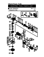
numbers in the descriptions below correspond to numbers in the Parts List and exploded
assembly diagrams for the Models G 12VA, G 13VA, G 13YF; the
<Bold>
numbers correspond to those in
the Parts List and exploded assembly diagrams for the Models G 15VA and G 15YF.
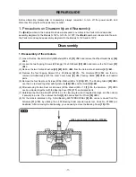
1. Disassembly of the armature
(1) Loosen the Hex. Socket Hd. Bolt (W/Washers) M5 x 20
[31] <32>
and remove the Wheel Guard Ass’y
[34]
<35>
.
(2) Loosen the two Tapping Screws (W/Flange) D4 x 50 (Black)
[59] <60>
and remove the Tail Cover
[57]
<58>
.
(3) Remove the two Carbon Brushes
[42]
,
[43] <43>
,
<44>
from the Carbon Brush Holders
[41] <42>
.
(4) Remove the four Tapping Screws D5 x 25 (Black)
[2] <1>
. The Armature
[11] <12>
can then be
removed simultaneously with the Gear Cover Ass'y
[4] <5>
, Packing Gland
[25] <26>
, and related
parts.
(5) Remove the four Seal Lock Screws (W/Sp. Washer) M5 x 16
[26] <27>
. The Packing Gland
[25] <26>
can then be removed together with Spindle (A)
[28] <29>
and the Gear
[19] <20>
.
(6) After removing the two Seal Lock Screws (W/Sp. Washer) M4 x 10
[1] <3>
, the Armature
[11] <12>
can be extracted together with the Bearing Cover
[10] <11>
and related parts.
(7) Carefully wrap the Armature
[11] <12>
in a soft, clean rag to protect it against damage, and then clamp
it securely in a vise. Then remove the Nut
[5] <6>
and extract the Pinion
[19] <20>
.
(8) For the models indicated in Fig. 3, Ball Bearing 629T12DDC3PS2-L
[8] <9>
can be removed from the
Armature
[11] <12>
by utilizing the J-204 Bearing Puller (special repair tool, Code No. 970982) as
illustrated. After removing the ball bearing, you can easily remove the Bearing Cover
[10] <11>
.
Disassembly
REPAIR GUIDE
Fig. 3
J204 bearing puller (Code No. 970982)

