-13-
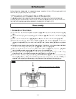
4. Removal of the controller and the snap switch
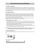
(1) Loosen the two Tapping Screws (W/Flange) D4 x 50 (Black)
[59] <60>
and remove the Tail Cover
[57] <58>
.
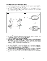
(2) Turn the Controller
[53] <54>
for the Housing
[39] <40>
in the arrow "A" direction, and then remove the
Controller
[53] <54>
from the Housing
[39] <40>
. (Fig. 5)
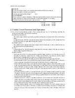
(3) While pressing the Switch
[49] <50>
in the arrow "A" direction, use a small flat-blade screwdriver to
press the latches of the Controller
[53] <54>
in the arrow "B" direction to remove the snap Switch
[49]
<50>
from the Controller
[53] <54>
. (Fig. 6)
5. Disassembly of the stator
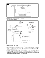
(1) After removing the Armature
[11] <12>
, disconnect the lead wires connected to the carbon Brush
Holders
[41] <42>
, and then remove the Connector 50091
[52] <53>
.
(2) Remove the Fan Guide
[12] <13>
from the Housing
[39] <40>
.
(3) Loosen the two Hex. Hd. Tapping Screws D4 x 70
[13] <14>
, and then remove the Stator
[14] <15>
and
Internal Wire
[51] <52>
from the Housing
[39] <40>
. If the Stator
[14] <15>
proves difficult to remove
from the Housing
[39] <40>
, use an appropriate heating device to heat the Housing
[39] <40>
to a
temperature of about 60
C (140
F) in order to facilitate disassembly.
6. Removal of the slide switch knob
(1) Loosen the two Tapping Screws (W/Flange) D4 x 50 (Black)
[59] <60>
and remove the Tail Cover
[57] <58>
.
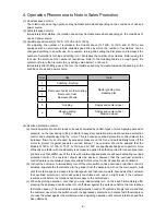
(2) Hold the Housing
[39] <40>
and remove the Spring
[46] <47>
, and then raise the Slide Bar
[47] <48>
until the Slide Switch Knob
[38] <39>
moves to the "ON" position.
(3) Check that the Slide Switch Knob
[38] <39>
has not moved to the "ON-LOCK" position, and then push
down the Slide Switch Knob
[38] <39>
until it clicks while keeping the Slide Bar
[47] <48>
raised.
(4) Raise the Slide Switch Knob
[38] <39>
straight up and remove it while keeping the Slide Bar
[47] <48>
raised.
Fig. 5
Fig.
6


