6 - 12
6-2-2 Test Equipment, Power Supply and Charts for Adjustment
1) Color bar chart
2) 3100 K light box (maintenance is necessary)
3) Backfocus chart
4) Color monitor (color TV with AV input jacks)
5) Oscilloscope
6) Vectorscope
7) Digital voltmeter
8) Frequency counter
9) DC power supply for DSP-R jig (5 V/1 A)
Information:
It is recommended that you use a vectorscope when
performing the chroma gain adjustment.
You can use an oscilloscope instead: Note, however, that
the adjustment accuracy will be lower.
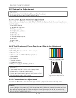
Fig. 6-2-1 Color Bar Chart
Fig. 6-2-2 Backfocus Chart
6-2-3 Connections for Adjustment
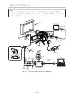
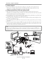
Connect the DVD video camera/recorder, jigs and test equipment as shown in the Fig. 6-2-3.
Caution
It is very dangerous to perform any work with the DVD video camera/recorder disassembled, since the
DVD video camera/recorder has a laser-emitting block and high-voltage circuits: Do not remove any
parts other than the adjustment cover.
Adjustment > Setups for Adjustment
6-2 Setups for Adjustment
Restrictions:
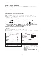
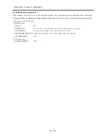
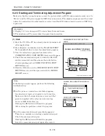
Be sure to perform "6-1-1 Checking Reference Data" in advance.
No adjustment can be done without reference data.
6-2-1 List of Jigs and Tools for Adjustment
Same as when creating reference data: Refer to “6-1-2 List of jigs and tools when creating reference
data” for details.
1) Personal computer
2) Adjustment fl oppy disc
3) Halcyon connector
4) C12 light balance fi lter
5) DSP-R Jig
6) RS-232C cable
7) AV/S input/output cable
8) DZ-ACS3
9) Power cable
10) DC power cord


