12
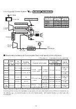
2.3.3 Capacity Control System
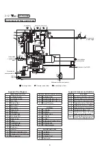
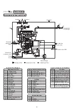
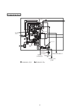
Air-Cooled
Water-Cooled
Air intake
Air Intake filter
1st-stage
airend
Intercooler
Check valve
Aftercooler
Blowoff
silencer
Pressure sensor
Air
discharge
1st-stage blowoff solenoid valve (1)
2nd-stage blowoff solenoid valve (1)
2nd-stage blowoff solenoid valve (2)
1st-stage blowoff solenoid valve (2)
2nd-stage
airend
PS2
Purging Air Flow and Action of Blowoff Solenoid Valve
Operation phase Blowoff solenoid
valve (1)
Blowoff solenoid
valve (2)
Starting
Fully opened
Fully closed
Loading
Fully closed
Fully closed
Purging
Fully opened
Fully closed
Stop
Fully opened
Fully opened
Power Interruption
Fully closed
Fully opened
■
Relationship between Air Consumption Rate and Capacity Control System
※
The value in ( ) is indicated for water-cooled type.
Model
Rated
pressure
psi [MPa]
Air
consumption
(%)
Operating
frequency (Hz)
Capacity control system
Pressure setting
psi [MPa]
Capacity
control type
Initial
Example
of Lower
55 kW
125 [0.86]
100 - 75 (65) 134 (136) - 108 (108)
①
CPCS
motor
speed control
Control
pressure 125 [0.86] 120 [0.83]
AUTO ON
VSDA
or
AUTO OFF
VSDB
75 kW
100 - 60 (50) 133 (137) - 80 (72)
55 kW
125 [0.86]
75 (65) - 5
82
②
Two-step purge
control
Cut-out
pressure 138 [0.95] 125 [0.86]
AUTO ON
VSDA
or
AUTO OFF
VSDB
75 kW
60 (50) - 5
66 (60)
Cut-in
pressure 131 [0.90] 120 [0.83]
All
model
125 [0.86]
5 - 0
Main motor stop
③
Motor
stop/
restart control
Cut-in
pressure 131 [0.90] 120 [0.83]
AUTO ON
VSDA
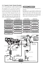
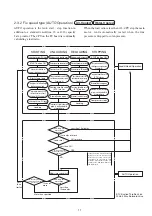
The air compressor supports the three (3) capacity control systems as shown above.
Depending on the varying air consumption, an appropriate system is automatically selected. For more information, see
the following page. Operation frequency is shown by Digital monitor. LCD monitor displays up to first figure after
decimal place.


