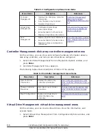
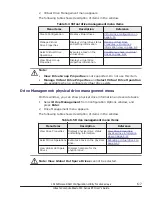
background image

Message

Description

b

.

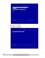
Press the ESC key.
The selection window appears.

c

.

Press the Y key.
System startup continues.

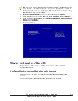
The following VDs have missing

disks:
If you proceed (or load the

configuration utility), these VDs is

marked OFFLINE and are

inaccessible.
Check your cables and ensure all

disks are present.
Press any key to continue or press

C to load the configuration utility.

Cause:

The logical drive is set to Offline because some

physical drives are not recognized.

Action 1:

a

.

Enter a character, and then press the Enter

key.
The following message appears: Critical

Message handling completed. Please exit.

b

.

Press the ESC key.
The selection window appears.

c

.

Press the Y key.
System startup continues.

Action 2:

a

.

Press the C key, and then press the Enter

key.

b

.

The LSI MegaRAID <HITACHI SAS 3004

iMR ROMB> Configuration Utility restarts.

Action 3:

If this message is displayed even though the

physical drive is properly mounted, contact your

reseller or call maintenance personnel.

The firmware version inconsistency

was detected.
The adapter was recovered, but

cached data was lost.
Press any key to continue or press

C to load the configuration utility.

Cause:

An inconsistency in firmware versions was

detected.

Action 1:

a

.

Enter a character, and then press the Enter

key.
The following message appears: Critical

Message handling completed. Please exit.

b

.

Press the ESC key.
The selection window appears.

c

.

Press the Y key.
System startup continues.

Action 2:

a

.

Press the C key, and then press the Enter

key.

b

.

The LSI MegaRAID <HITACHI SAS 3004

iMR ROMB> Configuration Utility restarts.

Action 3:

If this message appeared, contact your reseller

or call maintenance personnel.

5-64

SAS 3004 iMR ROMB Configuration Utility

Hitachi Compute Blade 500 Series EFI User's Guide

Summary of Contents for Compute Blade 500 Series

Page 1: ...Hitachi Compute Blade 500 Series EFI User s Guide MK 91CB500024 13 Document Organization Product Version Getting Help Contents ...

Page 2: ...conditions of the applicable Hitachi Data Systems Corporation agreements The use of Hitachi Ltd products is governed by the terms of your agreements with Hitachi Data Systems Corporation Hitachi is a registered trademark of Hitachi Ltd in the Rollback Configuration United States and other countries Hitachi Data Systems is a registered trademark and service mark of Hitachi Ltd in the United States ...

Page 3: ...iSCSI 1 5 iSCSI initiator 1 6 iSCSI target 1 6 Fibre channel mezzanine card BIOS 1 6 2 UEFI setup menu 2 1 Configuration of UEFI setup menu 2 2 Key functions for UEFI setup menu 2 3 Starting UEFI setup menu 2 3 UEFI setup menu window 2 3 UEFI setup menu items CB 520H A1 B1 2 5 System Configuration and Boot Management 2 5 Storage expansion blade settings 2 19 UEFI setup menu items CB 520H B2 2 21 S...

Page 4: ...8 Main menu 3 9 Switching display modes 3 23 Building disk arrays 3 24 Building disk arrays 3 25 BIOS settings enabled or disabled 3 50 Exiting MegaRAID WebBIOS 3 54 Disk with foreign configuration 3 56 Status 3 58 Status of the disk array 3 58 Status of the disk 3 58 BIOS messages 3 58 4 MegaRAID WebBIOS for storage expansion blades 4 1 Configuration of MegaRAID WebBIOS 4 2 Operation for MegaRAID...

Page 5: ... 5 52 Status of the virtual drive 5 52 Status of the physical drive 5 52 Error messages at the system boot 5 53 6 LSI Software RAID Configuration Utility for disk arrays 6 1 Flowchart of the utility 6 3 Key operation for the utility 6 3 Starting the utility 6 4 Window configuration of the utility 6 5 Configuration Options configuration options menu 6 5 Controller Management disk array controller m...

Page 6: ... SAS configuration utility 7 4 Main menu 7 5 Basic information 7 6 SAS topology 7 9 RAID properties 7 15 Exiting SAS configuration utility 7 31 8 BIOS settings for PXE boot 8 1 Requirements for PXE boot 8 2 PXE boot settings 8 2 Emulex PXE BIOS settings 8 3 Boot Order settings using UEFI menu 8 4 9 iSCSI settings 9 1 iSCSI settings flow chart 9 2 Personality settings 9 2 Starting PXESelect Utility...

Page 7: ...dure of Personality 10 2 Connecting to FCoE device for booting 10 3 Setting for FCoE boot FCoE BIOS 10 3 Canceling procedure of FCoE boot setting FCoE BIOS 10 9 vii Hitachi Compute Blade 500 Series EFI User s Guide ...

Page 8: ...viii Hitachi Compute Blade 500 Series EFI User s Guide ...

Page 9: ...cts is governed by the terms of your agreement s with Hitachi Data Systems This preface includes the following information Intended Audience Product Version Release Notes Document Organization Referenced Documents Document Conventions Convention for storage capacity values Getting Help Comments Preface ix Hitachi Compute Blade 500 Series EFI User s Guide ...

Page 10: ...k the chapter title in the left column to go to that chapter The first page of each chapter provides links to the sections in that chapter Chapter Description Chapter 1 UEFI and BIOS Configuration Overview Describes the UEFI disk array utilities and Fibre Channel mezzanine card BIOS configuration overview Chapter 2 UEFI setup menu Describes UEFI setup menu items Chapter 3 MegaRAID WebBIOS for LSI ...

Page 11: ...Guide for Red Hat Enterprise Linux MK 99COM141 Hitachi Compute Blade 500 OneCommandManager Guide MK 91CB500031 Server installation and monitoring tool User s Guide internal storage monitoring functions Hitachi Gigabit Fibre Channel Adapter USER S GUIDE BIOS EFI Edition MK 99COM009 Hitachi Compute Blade Emulex Adapter User s Guide for Hardware MK 99COM104 Document Conventions This term Compute Blad...

Page 12: ...UTION This indicates the presence of a potential risk that might cause relatively mild or moderate injury NOTICE This indicates the presence of a potential risk that might cause severe damage to the equipment and or damage to surrounding properties Note This indicates notes not directly related to injury or severe damage to equipment Tip This indicates advice on how to make the best use of the equ...

Page 13: ...a Systems customer support staff is available 24 hours a day seven days a week If you need technical support log on to the Hitachi Data Systems Portal for contact information https portal hds com Comments Please send us your comments on this document doc comments hds com Include the document title and number including the revision level for example 07 and refer to specific sections and paragraphs ...

Page 14: ...xiv Preface Hitachi Compute Blade 500 Series EFI User s Guide ...

Page 15: ...he UEFI disk array utilities and Fibre Channel mezzanine card BIOS configuration overview Overview UEFI Disk array utilities PXE boot iSCSI Fibre channel mezzanine card BIOS UEFI and BIOS Configuration Overview 1 1 Hitachi Compute Blade 500 Series EFI User s Guide ...

Page 16: ... iSCSI boot Using setup menus of BIOS for settings For the details see PXE boot on page 1 5 iSCSISELECT utilities Performs settings of controller in the server blade for using OS from iSCSI boot Using setup menus of utility for settings For the details see iSCSI on page 1 5 Fibre Channel mezzanine card BIOS Performs settings of mezzanine cards in the server blade using a setup menu of mezzanine ca...

Page 17: ...ured in the following form http IP address port number or https IP address port number The default port number http 80 https 443 3 Login the Web console of the management module 4 The following table describes the factory default account settings for the system administrator Table 1 3 Factory default account settings for the system administrator Item Factory default User ID administrator Password ...

Page 18: ...I disk array utilities Emulex PXE BIOS iSCSISELECT utilities and mezzanine card BIOS utilities after starting the remote console UEFI UEFI Unified EFI is the Firmware for a server blade You can use a server blade as default setting To change the boot order or other settings see Chapter 2 UEFI setup menu Disk array utilities One of the three utilities is used depending on the model or RAID controll...

Page 19: ...ter 4 Note 1 Not applicable PXE boot Preboot eXecution Environment PXE boot is the function that loads the image of OS or installer through network Performs the setting of Boot Order in Emulex PXE BIOS or UEFI menus for using PXE boot For the details see Chapter 8 BIOS settings for PXE boot iSCSI The iSCSI protocol defines the rules and processes for the iSCSI command send and receive through TCP ...

Page 20: ...s by connecting through iSCSI protocol iSCSI Data devices Dedicated data area for server blades is available on the external storage devices See Data device setting on page 9 12 for details iSCSI Boot devices OS boot from the device on the external storage devices is available See Boot device setting on page 9 9 for details Emulex PXE BIOS and iSCSISELECT Utility is used for iSCSI settings For det...

Page 21: ...EFI setup menu window UEFI setup menu items CB 520H A1 B1 UEFI setup menu items CB 520H B2 UEFI setup menu items CB 520H B3 UEFI setup menu items CB 520A A1 UEFI setup menu items CB 540A A1 B1 UEFI setup menu items CB 520X B1 UEFI setup menu items CB 520X B2 Software license information UEFI setup menu 2 1 Hitachi Compute Blade 500 Series EFI User s Guide ...

Page 22: ...Configuration of UEFI setup menu This section describes the UEFI setup menu items See the following chart Figure 2 1 UEFI setup menu 2 2 UEFI setup menu Hitachi Compute Blade 500 Series EFI User s Guide ...

Page 23: ... to power on a server blade 2 When F1 Setup is displayed in the bottom of the window during the server blade startup press F1 key Tip The following window appears when EFI firmware has started from the Secondary EFI ROM due to a Primary failure On this window press F1 key to start the setup menu as well 3 The setup menu is booted and System Configuration and Boot Management window will be displaye...

Page 24: ...UEFI setup menus appropriate for your server blade Model Reference CB 520H A1 B1 UEFI setup menu items CB 520H A1 B1 on page 2 5 CB 520H B2 UEFI setup menu items CB 520H B2 on page 2 21 CB 520H B3 UEFI setup menu items CB 520H B3 on page 2 39 CB 520A A1 UEFI setup menu items CB 520A A1 on page 2 57 CB 540A A1 B1 UEFI setup menu items CB 540A A1 B1 on page 2 74 CB 520X B1 UEFI setup menu items CB 5...

Page 25: ...ice selected on Boot Option Primary Boot Sequence Boot Manager Boot Manager Displays the boot priority order adds deletes a boot device changes the boot order sets boot from a file one time boot or resets the system System Event Logs Displays the system event logs display menu User Security Sets changes power on and administrative passwords Save Settings Saves the new settings Restore Settings Dis...

Page 26: ... the chipset with the server blade firmware version 01 95 or later Processor Details Displays summary of the installed processors Memory Memory Mode Displays the memory mode Memory Speed Displays the installed memory speed Total Memory Size Displays the total installed memory size Memory Voltage Displays the memory operating voltage Product Data Sub menu The following table shows description of me...

Page 27: ...r settings See Processors sub menu on page 2 7 Memory Displays and provides option to change the memory settings See Memory sub menu on page 2 9 Devices and I O Ports Displays devices and I O port options of settings See Device and I O Ports sub menu on page 2 26 Operating Modes Selects the operating mode desired based on your preference Legacy Support Selects the legacy support System Security Se...

Page 28: ...ute Disable Bit Disable Enable With Disable the response is always 0 for XD feature flag Intel Virtualization Technology Disable Enable Sets Vanderpool Technology which is Intel s new virtualization technology Hardware Prefetcher Disable Enable Sets Hardware Prefetcher Adjacent Cache Prefetch Disable Enable Sets Adjacent Cache Prefetch DCU Streamer Prefetcher Disable Enable Sets DCU Streamer Prefe...

Page 29: ...33 Force DDR3 1600 Sets the memory clock frequency Memory Power Management Disable Automatic Sets Memory Power Management Socket Interleave Non NUMA NUMA Sets a type of Memory Interleave Patrol Scrub Disable Enable Sets the patrol scrubbing which proactively searches the memory to repair correctable errors Memory Data Scrambling Disable Enable Sets the memory data scrambling Page Policy Closed Ope...

Page 30: ...nable When using TXT function on Vmware execute the following command at boot bootOption o The following table shows description of menu items appeared in the left side of the window Select the item to display or set and press Enter Table 2 9 System Security sub menu items Menu items Selection1 Description TPM Status TPM Physical Presence Displays the status of TPM Physical Presence TPM Device Sta...

Page 31: ...ion 01 59 or later TPM Force Clear Deletes the TPM data Note 1 A value in double angle brackets shows the default TPM device settings Enable the status of Trusted Platform Module TPM device Use the following procedure for enabling the TPM Device 1 Confirm that TPM Physical Presence value is Asserted in the System Security sub menu 2 Select Disable of TPM Device and press Enter Enable is displayed ...

Page 32: ...tems Menu items Selection Description System Date Increases or decreases the setting value using keys Sets the local date of the system Sets the date as mm dd yyyy System Time Increases or decreases the setting value using keys Sets the local time of the system Sets the time as hh mm ss in the form of 24 hours Start Options Select an item to boot and press Enter Place the cursor on a device to boo...

Page 33: ...enu on page 2 14 Delete WOL Boot Option Deletes a device or file system from the WOL boot option which is enabled in the next boot See Delete Boot Option sub menu on page 2 14 Change WOL Boot Order Change the WOL boot orders which are enabled in the next boot See Change Boot Order sub menu on page 2 15 Boot Other Boot From File Boots up from a file that you specify Boot From Device Boots up from a...

Page 34: ...ay Select item to add and press Enter Note If you select unnecessary items it may lead to some troubles including longer boot time Tip To return to the Boot Manager highlight the target item and then press Enter and Esc twice Delete Boot Option sub menu Select the check box of the item to delete and press Enter And Select a Commit Changes and press Enter 2 14 UEFI setup menu Hitachi Compute Blade ...

Page 35: ... Legacy mode not to indicate target devices to boot For CB 520H A1 B1 we guarantee OS boot only in Legacy mode Thus do not delete Legacy Only Tip You can delete WOL Boot Option in Delete WOL Boot Option menu in the same way Change Boot Order sub menu Select an item to display or set and press Enter UEFI setup menu 2 15 Hitachi Compute Blade 500 Series EFI User s Guide ...

Page 36: ...h up down cursor keys change the order with keys and press Enter Commit Changes Commits changes You need to save the new settings before exiting from the setup menu Note Legacy Only is a flag to indicate booting from target devices displayed below in Legacy mode not to indicate target devices to boot For CB 520H A1 B1 we guarantee OS boot only in Legacy mode Thus place Legacy Only at the top of th...

Page 37: ...The following table shows description of menu items appeared in the left side of the window Select an item to set and press Enter Table 2 14 Boot Modes sub menu items Menu items Selection1 Description System Boot Mode UEFI and Legacy UEFI Only Legacy Only Sets which Boot Manager uses to boot UEFI Driver or Option ROM UEFI Only Uses UEFI Driver Select this for OS boot in UEFI mode Legacy Only Uses ...

Page 38: ...he left side of the window Select an item to display or set and press Enter Table 2 15 User Security menu items Menu items Description Set Power On Password Sets a power on password Clear Power On Password Deletes a power on password Set Admin Password Sets an administrator password Clear Admin Password Deletes an administrator password Note Once a password is set you need to enter the password wh...

Page 39: ...ve And Exit the Setup Utility is appeared And then press Y to save changed settings and exit Storage expansion blade settings When installing 1 Gb 4 port 8 port LAN mezzanine card in the mezzanine card slot 4 of a storage expansion blade follow the steps shown below Enable Disable Adapter Option ROM Support Follow steps below to disable OPROM for the mezzanine card slot 4 1 Start the remote consol...

Page 40: ... to step 9 7 Select Disable and press Enter 8 Confirm that I O Expansion 2 Dev 2 is Disable 9 Press ESC key three times to get back to System Configuration and Boot Management Select Save Settings and press Enter 10 Select Exit Setup and press Enter 11 Press Y key to exit Setup Utility 2 20 UEFI setup menu Hitachi Compute Blade 500 Series EFI User s Guide ...

Page 41: ... date and time of the system Start Options Executes boot from a device selected on Boot Option Primary Boot Sequence Boot Manager Boot Manager Displays the boot priority order adds deletes a boot device changes the boot order sets boot from a file one time boot or resets the system System Event Logs Displays the system event logs display menu User Security Sets changes power on and administrative ...

Page 42: ...ackages Processor Speed Displays the processor speed QPI Link Speed Displays the QPI link speed Chipset Model Displays the detailed information of the chipset with the server blade firmware version 04 30 or later Processor Details Displays summary of the installed processors Memory Memory Mode Displays the memory mode Memory Speed Displays the installed memory speed Total Memory Size Displays the ...

Page 43: ...essor settings See Processors sub menu on page 2 24 Memory Displays and provides option to change the memory settings See Memory sub menu on page 2 25 Devices and I O Ports Displays devices and I O port options of settings See Device and I O Ports sub menu on page 2 26 Operating Modes Selects the operating mode desired based on your preference Legacy Support Selects the legacy support System Secur...

Page 44: ...es Disable Enable Sets a CPU power saving mode which is enabled after the reboot Package ACPI C State Limit ACPI C2 ACPI C3 Sets a C State upper limit in the CPU idle mode Not displayed when C States is disabled C1 Enhanced Mode Disable Enable Sets CPU Enhanced C1E State which is enabled after the reboot Hyper Threading Disable Enable Sets CPU Hyper Threading Shown only when supported by installed...

Page 45: ...m Memory Details Displays the status of each system memory See System Memory Details on page 2 26 Total Memory Size Displays the total memory size Memory Voltage Displays the memory operating voltage Memory Mode Independent Mirroring Sparing Selects a memory operating mode Memory Speed Auto Force DDR3 800 Force DDR3 1066 Force DDR3 1333 Force DDR3 1600 Force DDR3 1866 Sets a maximum value on memor...

Page 46: ... the server blade firmware version 04 15 or later Rank Margining Test Disable Enable Sets the memory rank margin test Note 1 A value in double angle brackets shows the default System Memory Details Select a processor and press Enter Then details of memory connected to the processor Tip EMPTY DIMM is not installed in the DIMM slot Present Enabled DIMM is available Device and I O Ports sub menu Sele...

Page 47: ...23 Device and I O Ports sub menu items Menu items Selection1 Description Active Video Onboard Device Add in Device Specifies a destination to output video PCI Express Native Control Disable Enable Enables or disables direct control of PCI Express by OS This item is displayed with the server blade firmware version 04 22 or later PCI 64 Bit Resource Allocation Disable Enable Enables or disables 64 b...

Page 48: ...t side of the window Select the item to display or set and press Enter Table 2 24 System Security sub menu items Menu items Selection1 Description TPM Status TPM Physical Presence Displays the status of TPM Physical Presence TPM Device State Displays TPM Device State TPM TXT Status Displays TPM Trusted Execution Technology TXT Status MOR Status Displays MOR memory overwrite request status Refresh ...

Page 49: ...tate and press Enter Enable is displayed and press Enter again 6 Operation success require reboot to take effect is displayed TPM is activated after rebooting the server blade RAS Configuration sub menu Select an item to display or set and press Enter Note When the default value of any item has been changed in this sub menu it may take longer for the system boot after you return all setting values...

Page 50: ...ansion blade Note 1 A value in double angle brackets shows the default Date and Time Select an item to display or set and press Enter The following table shows description of menu items appeared in the left side of the window Select an item to display or set and press Enter Table 2 27 Data and Time menu items Menu items Selection Description System Date Increases or decreases the setting value usi...

Page 51: ...age 2 32 Delete Boot Option Deletes a device or file system from the boot option which is enabled in the next boot See Delete Boot Option sub menu on page 2 33 Change Boot Order Changes boot orders which are enabled in the next boot See Change Boot Order sub menu on page 2 33 Secondary WOL Boot Sequence Add WOL Boot Option Adds a device or file system to the WOL boot option See Add Boot Option sub...

Page 52: ...er in this case Add Boot Option sub menu Select Generic Boot Option and press Enter Note You can only add Standard Boot Options Do not add Advanced Boot Options Tip You can add new WOL Boot Option to the Add WOL Boot Option menu in the same way Select item to add and press Enter Note If you select unnecessary items it may lead to some troubles including longer boot time Tip To return to the Boot M...

Page 53: ...s a flag to indicate booting from target devices displayed below in Legacy mode not to indicate target devices to boot For CB 520H B2 we guarantee OS boot only in Legacy mode Thus do not delete Legacy Only Tip You can delete WOL Boot Option in Delete WOL Boot Option menu in the same way Change Boot Order sub menu Select an item to display or set and press Enter UEFI setup menu 2 33 Hitachi Compute...

Page 54: ...ith up down cursor keys change the order with keys and press Enter Commit Changes Commits changes You need to save the new settings before exiting from the setup menu Note Legacy Only is a flag to indicate booting from target devices displayed below in Legacy mode not to indicate target devices to boot For CB 520H B2 we guarantee OS boot only in Legacy mode Thus place Legacy Only at the top of the...

Page 55: ...cription of menu items appeared in the left side of the window Select an item to display or set and press Enter Table 2 30 Boot Modes sub menu items Menu items Selection1 Description System Boot Mode UEFI and Legacy UEFI Only Legacy Only Selects which to be used UEFI Driver or Option ROM by Boot Manager UEFI and Legacy Tries to boot in UEFI mode If it fails tries to boot in Legacy mode UEFI Only U...

Page 56: ... User Security menu items Menu items Description Set Power On Password Sets a power on password Clear Power On Password Deletes a power on password Set Admin Password Sets an administrator password Clear Admin Password Deletes an administrator password Note Once a password is set you need to enter the password when completing the system boot or accessing Configuration Setup menu With configuration...

Page 57: ...ing 1 Gb 4 port 8 port LAN mezzanine card in the mezzanine card slot 4 of a storage expansion blade follow the steps shown below Enable Disable Adapter Option ROM Support Follow steps below to disable OPROM for the mezzanine card slot 4 1 Start the remote console and then click Power Power On to power on the server blade with storage expansion blade 2 Press F1 key while F1 Setup is being displayed...

Page 58: ...ESC key three times to get back to System Configuration and Boot Management Select Save Settings and press Enter 10 Select Exit Setup and press Enter 11 Press Y key to exit Setup Utility 2 38 UEFI setup menu Hitachi Compute Blade 500 Series EFI User s Guide ...

Page 59: ...ime of the system Start Options Selects the boot target from the boot options in Primary Boot Sequence of the Boot Manager menu and starts booting Boot Manager Displays the boot priority order adds deletes a boot device changes the boot order sets boot from a file one time boot or resets the system System Event Logs Displays the system event logs display menu User Security Sets changes power on an...

Page 60: ...tion Host Firmware Version Displays the UEFI version Build Date Displays the UEFI build date BMC Version Displays the BMC version Build Date Displays the BMC build date System Summary Sub menu The following table shows description of menu items displayed in the left side of the window Table 2 35 System Summary menu items Menu items Description System Identification Data Machine Type Model Displays...

Page 61: ...dware to set the following two items Network Storage For details about Hitachi Gigabit fibre channel adapter however see the Hitachi Gigabit Fibre Channel Adapter USER S GUIDE BIOS EFI Edition to set the following two items Adapters and UEFI Drivers Storage The following table shows description of menu items displayed in the left side of the window Table 2 36 System Settings menu items Menu items ...

Page 62: ...o display or set and press Enter Table 2 37 Devices and I O Ports menu items Menu items Selection1 Description Active Video Onboard Device Add in Device If Add in Device is selected video will be switched from onboard video to an add in video adapter and the onboard video will be disabled before booting into OS If Onboard Device is selected an add in video adapter can be used as the secondary vide...

Page 63: ... USB Configuration Settings See USB Configuration on page 2 43 Note 1 A value in double angle brackets shows the default USB Configuration Select an item to display or set and press Enter The following table shows description of menu items appeared in the left side of the window Table 2 38 USB Configuration items Menu items Selection1 Description Front Dongle USB Port 1 Disable Enable USB Configur...

Page 64: ...e2 Independent Mirroring Selects a memory operating mode Sparing2 Disable Enable Select whether to enable memory sparing Memory Speed Auto Force DDR4 1600 Force DDR4 1866 Force DDR4 2133 Sets a maximum value on memory clock frequency Memory Power Management Disable Automatic Sets Memory Power Management Socket Interleave Non NUMA NUMA Sets Memory Socket Interleave Patrol Scrub Enable Disable Sets ...

Page 65: ... When Mirroring is enabled you cannot set Sparing Conversely when Sparing is enabled you cannot set Mirroring System Memory Details Place the cursor on a processor to display and press Enter Tip Currently installed processors are displayed on the window Select a processor to show the details of memory connected to the processor UEFI setup menu 2 45 Hitachi Compute Blade 500 Series EFI User s Guide...

Page 66: ... DIMM group per memory controller to disable or enable and press Enter Processors sub menu Select an item to display or set and press Enter Note Do not change the settings of other than the following items If you change the settings UEFI may not start up 2 46 UEFI setup menu Hitachi Compute Blade 500 Series EFI User s Guide ...

Page 67: ...ch is enabled after the reboot C1 Enhanced Mode Disable Enable Sets CPU Enhanced C1E State which is enabled after the reboot Hyper Threading Enable Disable Sets CPU Hyper Threading Shown only when supported by installed CPUs Execute Disable Bit Disable Enable With Disable the response is always 0 for XD feature flag Enable TXT Disable Enable Sets Trusted Execution Technology VMX Disable Enable Set...

Page 68: ...e Cores in CPU Package All 1 17 Sets running cores in the CPU package QPI Link Frequency Minimal Power Balanced Max Performance Sets the number of clock frequencies in Quick Path Interconnect QPI Link Turbo Limits Full turbo uplift Restrict turbo Can be used to limit the Maximum turbo frequency Note 1 A value in double angle brackets shows the default Recovery and RAS sub menu Select an item to di...

Page 69: ...isable Enable Sets PCIe isolation Deconfigured Mode Disable Enable Sets the Deconfigured mode POST Fail Retry Disable Enable Enable or Disable POST Fail Retry POST Retry is performed automatically when EFI firmware detects any memory failure at POST Note 1 A value in double angle brackets shows the default 2 These items are displayed but are not available Security sub menu Place the cursor on a me...

Page 70: ... to display or set and press Enter Table 2 44 System Security sub menu items Menu items Selection1 Description TPM Status TPM Physical Presence Displays the status of TPM Physical Presence TPM Device State Displays TPM Device State MOR Status Displays MOR memory overwrite request status This item is displayed with EFI firmware version 04 00 or later Refresh TPM Status Refreshes the display of TPM ...

Page 71: ...ate and Time Select an item to display or set and press Enter The following table shows description of menu items displayed in the left side of the window Select an item to display or set and press Enter Table 2 45 Data and Time menu items Menu items Selection Description System Date Increases or decreases the setting value using keys Sets the local date of the system Sets the date as mm dd yyyy S...

Page 72: ...Boot Order Changes boot orders which are enabled in the next boot See Change Boot Order sub menu on page 2 54 Secondary WOL Boot Sequence Add WOL Boot Option Adds a device or file system to the WOL boot option See Add Boot Option sub menu on page 2 53 Delete WOL Boot Option Deletes a device or file system from the WOL boot option which is enabled in the next boot See Delete Boot Option sub menu on...

Page 73: ...d it to Boot Option for both Primary Boot Sequence and Secondary WOL Boot Sequence Select Add Boot Option in a category depending on your purpose Select item to add and press Enter Note Do not add unnecessary items which may cause lead to some troubles including longer boot time Tip To return to the Boot Manager highlight the target item and then press Enter and Esc twice Delete Boot Option sub me...

Page 74: ...may occur such as boot failure Tip You can delete WOL Boot Option in Delete WOL Boot Option menu in the same way Change Boot Order sub menu Select an item to display or set and press Enter 2 54 UEFI setup menu Hitachi Compute Blade 500 Series EFI User s Guide ...

Page 75: ...t order To change orders select and highlight a device with up down cursor keys change the order with keys and press Enter Commit Changes Commits changes You need to save the new settings before exiting from the setup menu System Event Logs The System Event Logs of server blade are displayed User Security Select an item to display or set and press Enter The following table shows description of men...

Page 76: ...tings Restore Settings Select Restore Settings and press Enter to cancel the change in settings and to restore to the previous settings Load Default Settings Select Load Default Settings and press Enter to cancel the change in settings and to restore to the factory default settings Note The following phenomena occur when a server blade carries Broadcom 1Gb 4p 8p LAN mezzanine cards When you execut...

Page 77: ...stem settings Data and Time Sets the local date and time of the system Start Options Executes boot from a device selected on Boot Option Primary Boot Sequence Boot Manager Boot Manager Displays the boot priority order adds deletes a boot device changes the boot order sets boot from a file one time boot or resets the system System Event Logs Displays the system event logs display menu User Security...

Page 78: ...ays the number of installed processor packages Processor Speed Displays the processor speed QPI Link Speed Displays the QPI link speed Processor Details Displays summary of the installed processors Memory Memory Mode Displays the memory mode Memory Speed Displays the installed memory speed Total Memory Size Displays the total installed memory size Memory Voltage Displays the memory operating volta...

Page 79: ...ems appeared in the left side of the window Table 2 53 System Settings menu items Menu items Description Adaptors and UEFI Drivers Displays information about adapters and UEFI drivers on the server blade Processors Displays and provides option to change the processor settings See Processors sub menu on page 2 60 Memory Displays and provides option to change the memory settings See Memory sub menu ...

Page 80: ...e C1 Enhanced Mode Disable Enable Sets CPU Enhanced C1E State which is enabled after the reboot Hyper Threading Disable Enable Sets CPU Hyper Threading Shown only when supported by installed CPUs Execute Disable Bit Disable Enable With Disable the response is always 0 for XD feature flag Intel Virtualization Technology Disable Enable Sets Vanderpool Technology which is Intel s new virtualization t...

Page 81: ...otal Memory Size Displays the total memory size Memory Voltage Displays the memory operating voltage Memory Mode Independent Mirroring Sparing Selects a memory operating mode Memory Speed Force DDR3 800 Force DDR3 1333 Force DDR3 1600 Sets a maximum value on memory clock frequency Memory Power Management Disable Automatic Sets Memory Power Management Socket Interleave Non NUMA NUMA Sets Socket Int...

Page 82: ... installed in the DIMM slot Present Enabled DIMM is available System Security sub menu Select an item to display or set on Trusted Platform Module TPM 1 2 and press Enter Note Do not change the settings of the following item If you change the settings in a poor attempt UEFI may not start up TXT State The following table shows description of menu items appeared in the left side of the window Select...

Page 83: ...shows the default TPM device settings Enable the status of Trusted Platform Module TPM device Use the following procedure for enabling the TPM Device 1 Confirm that TPM Physical Presence value is Asserted in the System Security sub menu 2 Select Disable of TPM Device and press Enter Enable is displayed and press Enter again 3 Success Reboot required to enable this change is displayed 4 TPM State m...

Page 84: ...es the setting value using keys Sets the local date of the system Sets the date as mm dd yyyy System Time Increases or decreases the setting value using keys Sets the local time of the system Sets the time as hh mm ss in the form of 24 hours Start Options Select an item to boot and press Enter Place the cursor on a device to boot and press Enter OS will be booted from the selected device The items...

Page 85: ...ice or file system from the WOL boot option which is enabled in the next boot See Delete Boot Option sub menu on page 2 66 Change WOL Boot Order Change the WOL boot orders which are enabled in the next boot See Change Boot Order sub menu on page 2 67 Boot Other Boot From File Boots up from a file that you specify Boot From Device Boots up from a device that you specify See Boot From Device sub men...

Page 86: ...ry items it may lead to some troubles including longer boot time Tip To return to the Boot Manager highlight the target item and then press Enter and Esc twice Delete Boot Option sub menu Select an item to delete and press the space key Then X appears in the square brackets And Select Commit Changes and press Enter to delete the device from Boot Option 2 66 UEFI setup menu Hitachi Compute Blade 50...

Page 87: ...in Legacy mode not to indicate target devices to boot For CB 520A A1 we guarantee OS boot only in Legacy mode Thus do not delete Legacy Only Tip You can delete WOL Boot Option in Delete WOL Boot Option menu in the same way Change Boot Order sub menu Select an item to display or set and press Enter UEFI setup menu 2 67 Hitachi Compute Blade 500 Series EFI User s Guide ...

Page 88: ...up down cursor keys change the order with keys and press Enter Commit Changes Commits changes You need to save the new settings before exiting from the setup menu Note Legacy Only is a flag to indicate booting from target devices displayed below in Legacy mode not to indicate target devices to boot For CB 520A A1 we guarantee OS boot only in Legacy mode Thus place Legacy Only at the top of the Boo...

Page 89: ...lowing table shows description of menu items appeared in the left side of the window Select an item to display or set and press Enter Table 2 61 Boot Modes sub menu items Menu items Selection1 Description System Boot Mode UEFI and Legacy UEFI Only Legacy Only Sets which Boot Manager uses to boot UEFI Driver or Option ROM UEFI Only Uses UEFI Driver Select this for OS boot in UEFI mode Legacy Only U...

Page 90: ...he left side of the window Select an item to display or set and press Enter Table 2 62 User Security menu items Menu items Description Set Power On Password Sets a power on password Clear Power On Password Deletes a power on password Set Admin Password Sets an administrator password Clear Admin Password Deletes an administrator password Note Once a password is set you need to enter the password wh...

Page 91: ...ve And Exit the Setup Utility is appeared And then press Y to save changed settings and exit Storage expansion blade settings When installing 1 Gb 4 port 8 port LAN mezzanine card in the mezzanine card slot 4 of a storage expansion blade follow the steps shown below Enable Disable Adapter Option ROM Support Follow steps below to disable OPROM for the mezzanine card slot 4 1 Start the remote consol...

Page 92: ...r When Disable is already selected go to step 9 7 Select Disable and press Enter 8 Confirm that I O Expansion 2 Dev 2 is Disable 9 Press ESC key three times to get back to System Configuration and Boot Management Select Save Settings and press Enter 2 72 UEFI setup menu Hitachi Compute Blade 500 Series EFI User s Guide ...

Page 93: ...able Software RAID 1 When F1 Setup is shown on the bottom of the window during server blade startup press F1 key 2 Select System Settings and press Enter 3 When System Settings menu appears select Devices and I O Ports and press Enter 4 When Devices and I O Ports menu appears select Enable Disable Onboard Device s and press Enter 5 When Enable Disable Onboard Device s menu appears select SCU Contr...

Page 94: ...etup menu items CB 540A A1 B1 This section describes UEFI setup menu items for CB 540A A1 B1 System Configuration and Boot Management Select an item to display or set and press Enter The following table shows description of menu items appeared in the left side of the window 2 74 UEFI setup menu Hitachi Compute Blade 500 Series EFI User s Guide ...

Page 95: ... new settings Restore Settings Discards any changes you made and restore to the original settings Load Default Settings Returns settings to the default values Exit Setup Exits the Setup menu System Information Select an item to display or set and press Enter The following table shows description of menu items appeared in the left side of the window Table 2 64 System Information menu items Menu ite...

Page 96: ...ory operating voltage Product Data Sub menu The following table shows description of menu items appeared in the left side of the window Table 2 66 Product Data menu items Menu items Description Host Firmware Build ID Displays the UEFI build ID number Version Displays the UEFI version Build Date Displays the UEFI build date System Settings Select an item to display or set and press Enter Note Do no...

Page 97: ...Selects this option to see all the Storage Device options Network Selects the Network setup options Processors sub menu Select an item to display or set and press Enter The following table shows description of menu items appeared in the left side of the window Select an item to display or set and press Enter Table 2 68 Processors menu items Menu items Selection1 Description Turbo Mode Disable Enab...

Page 98: ... Prefetcher Cores in CPU Package All 1 7 Sets the number of running cores in the CPU package Not shown with the server blade firmware version 03 10 or later QPI Link Frequency Minimal Power Balanced Max Performance Sets the number of clock frequencies in Quick Path Interconnect QPI Link Note 1 A value in double angle brackets shows the default Memory sub menu Select the item to display or set and ...

Page 99: ... NUMA or Non NUMA Patrol Scrub Disable Enable Sets the patrol scrubbing which proactively searches the memory to repair correctable errors Memory Data Scrambling Disable Enable Sets the memory data scrambling Page Policy Closed Open Adaptive Sets the memory page policy Rank Margining Test Disable Enable Sets the memory rank margin test Note 1 A value in double angle brackets shows the default Syst...

Page 100: ... MOR State The following table shows description of menu items appeared in the left side of the window Select the item to display or set and press Enter Table 2 70 System Security sub menu items Menu items Selection1 Description TPM Status TPM Physical Presence Displays the status of TPM Physical Presence TPM Device State Displays TPM Device State TPM TXT Status Displays TPM Trusted Execution Tech...

Page 101: ...or enabling the TPM Device 1 Confirm that TPM Physical Presence value is Asserted in the System Security sub menu 2 Select Disable of TPM Device and press Enter Enable is displayed and press Enter again 3 Operation success require reboot to take effect is displayed 4 TPM State menu is added in the System Security sub menu when TPM Device value is Enable 5 Select Deactivate of TPM State and press E...

Page 102: ...setting value using keys Sets the local time of the system Sets the time as hh mm ss in the form of 24 hours Start Options Select an item to boot and press Enter Select a device to boot and press Enter OS will be started the selected device The items to be displayed may be different depending on the setting of Boot Manager For the details see Boot Manager on page 2 82 Note When you boot from CD DV...

Page 103: ...4 Change WOL Boot Order Change the WOL boot orders which are enabled in the next boot See Change Boot Order sub menu on page 2 85 Boot Other Boot From File Boots up from a file that you specify Boot From Device Boots up from a device that you specify See Boot From Device sub menu on page 2 86 for details UEFI Shell Boots UEFI Shell Select Next One Time Boot Tries to boot from a specific target onl...

Page 104: ...ms it may lead to some troubles including longer boot time Tip To return to the Boot Manager highlight the target item and then press Enter and Esc twice Delete Boot Option sub menu Select the check box of the item to delete and press Enter And Select a Commit Changes and press Enter 2 84 UEFI setup menu Hitachi Compute Blade 500 Series EFI User s Guide ...

Page 105: ... Legacy mode not to indicate target devices to boot For CB 540A A1 B1 we guarantee OS boot only in Legacy mode Thus do not delete Legacy Only Tip You can delete WOL Boot Option in Delete WOL Boot Option menu in the same way Change Boot Order sub menu Select an item to display or set and press Enter UEFI setup menu 2 85 Hitachi Compute Blade 500 Series EFI User s Guide ...

Page 106: ...p down cursor keys change the order with keys and press Enter Commit Changes Commits changes You need to save the new settings before exiting from the setup menu Note Legacy Only is a flag to indicate booting from target devices displayed below in Legacy mode not to indicate target devices to boot For CB 540A A1 B1 we guarantee OS boot only in Legacy mode Thus place Legacy Only at the top of the B...

Page 107: ...ollowing table shows description of menu items appeared in the left side of the window Select an item to display or set and press Enter Table 2 75 Boot Modes sub menu items Menu items Selection1 Description System Boot Mode UEFI and Legacy UEFI Only Legacy Only Sets which Boot Manager uses to boot UEFI Driver or Option ROM UEFI Only Uses UEFI Driver Select this for OS boot in UEFI mode Legacy Only...

Page 108: ...he left side of the window Select an item to display or set and press Enter Table 2 76 User Security menu items Menu items Description Set Power On Password Sets a power on password Clear Power On Password Deletes a power on password Set Admin Password Sets an administrator password Clear Admin Password Deletes an administrator password Note Once a password is set you need to enter the password wh...

Page 109: ...enu Tip If you have unsaved changes Y Save And Exit the Setup Utility is appeared And then press Y to save changed settings and exit UEFI setup menu items CB 520X B1 This section describes UEFI setup menu items for CB 520X B1 System Configuration and Boot Management Select an item to display or set and press Enter The following table shows description of menu items displayed in the left side of th...

Page 110: ...display or set and press Enter The following table shows description of menu items displayed in the left side of the window Table 2 78 System Information menu items Menu items Description Node Detail Displays the node information only in SMP configuration Product Data Displays the product data See Product Data Sub menu on page 2 91 System Summary Displays the basic system information See System Su...

Page 111: ...nu items Description System Identification Data Not shown with the server blade firmware version 06 10 or later Machine Type Model Displays the machine type Serial Number Displays the serial number UUID Number Displays the UUID Asset Tag Number Displays the asset tag Processor Installed CPU packages Displays the number of installed processor packages Processor Speed Displays the processor speed QP...

Page 112: ...ft side of the window Table 2 82 System Settings menu items Menu items Description Adaptors and UEFI Drivers Displays information about adapters and UEFI drivers on the server blade Devices and I O Ports Displays devices and I O port options of settings Driver Health Displays the driver status Legacy Support Displays the legacy support setting window Memory Displays and provides option to change t...

Page 113: ...ss features from OS PCI 64 Bit Resource Allocation Disable Enable Enables or disables 64 bit resource allocation to PCI devices MM Config Base 1GB 2GB 3GB Sets the starting address of the PCI Express configuration space Intel VT for Directed I O VT d Enable Disable Enables or disables Intel VT for Directed I O VT d Enable Disable Onboard Device s Enables or disables devices Enable Disable Adapter ...

Page 114: ... Table 2 83 Memory menu items Menu items Selection1 Description System Memory Details Displays the status of each system memory See System Memory Details on page 2 95 Total Memory Size Displays the total memory size Memory Voltage Displays the memory operating voltage Memory Mode Lockstep Independent Selects a memory operating mode Memory Speed Auto Force DDR3 1066 Force DDR3 1333 Force DDR3 1600 ...

Page 115: ...an be disabled by this menu Memories can be disabled Enabled per memory controller See Memory Deconfigure Mode Details on page 2 97 Notes 1 A value in double angle brackets shows the default 2 If you change a setting of this item the EFI might not start Do not change any setting 3 When Mirroring is enabled you cannot set Sparing Conversely when Sparing is enabled you cannot set Mirroring System Me...

Page 116: ...e the cursor on a processor to display and press Enter Tip Currently installed processors are displayed on the window Select a processor to show the details of memory connected to the processor 2 96 UEFI setup menu Hitachi Compute Blade 500 Series EFI User s Guide ...

Page 117: ... in the DIMM slot Present Enabled DIMM is available Memory Deconfigure Mode Details Select a DIMM group per memory controller to disable or enable and press Enter UEFI setup menu 2 97 Hitachi Compute Blade 500 Series EFI User s Guide ...

Page 118: ...mit in the CPU idle mode Not displayed when C States is disabled C1 Enhanced Mode2 Disable Enable Sets CPU Enhanced C1E State which is enabled after the reboot Hyper Threading Enable Disable Sets CPU Hyper Threading Shown only when supported by installed CPUs Execute Disable Bit Disable Enable With Disable the response is always 0 for XD feature flag Intel Virtualization Technology2 Disable Enable...

Page 119: ...r set and press Enter The following table shows description of menu items displayed in the left side of the window Place the cursor on a menu to set and press Enter Table 2 85 Recovery and RAS sub menu items Menu items Selection Description Advanced RAS Sets the failure deconfiguration to CPU and DIMM See Advanced RAS for details Backup Bank Management Sets the backup management Disk GPT Recovery ...

Page 120: ...le or Disable POST Fail Retry POST Retry is performed automatically when EFI firmware detects any memory failure at POST Notes 1 A value in double angle brackets shows the default 2 These items are displayed but are not available Security sub menu Place the cursor on a menu to set and press Enter The following table shows description of menu items displayed in the left side of the window Select a ...

Page 121: ... or disables TPM Device TPM State Activate Deactivate Performs TPM Activation This item is only displayed when TPM Device is Enable MOR State Enable Disable Enable or Disable MOR memory overwrite request This item is displayed with EFI firmware version 04 00 or later TPM Force Clear Deletes the TPM data Note 1 A value in double angle brackets shows the default TPM device settings Enable the status...

Page 122: ...sing keys Sets the local time of the system Sets the time as hh mm ss in the form of 24 hours Start Options Select an item to boot and press Enter Select a target device to set boot and press Enter The target device will be booted first The items to be displayed may be different depending on the setting of Boot Manager For the details see Boot Manager on page 2 102 Boot Manager Select an item to d...

Page 123: ...L boot orders which are enabled in the next boot See Change Boot Order sub menu on page 2 105 Boot Other Boot From File Boots up from a specific device or file Boot From Device Boots up from a specific device path Select Next One Time Boot Tries to boot from a specific target only on the next boot System Boot Modes Displays the window to change system boot modes Reset System Restart the system Tip...

Page 124: ...oes not support the boot in Legacy Mode You can add a maximum of 10 items Tip To return to the Boot Manager highlight the target item and then press Enter and Esc twice Delete Boot Option sub menu Select the check box of the item to delete and press Enter And Select a Commit Changes and Exit and press Enter 2 104 UEFI setup menu Hitachi Compute Blade 500 Series EFI User s Guide ...

Page 125: ...may occur such as boot failure Tip You can delete WOL Boot Option in Delete WOL Boot Option menu in the same way Change Boot Order sub menu Select an item to display or set and press Enter UEFI setup menu 2 105 Hitachi Compute Blade 500 Series EFI User s Guide ...

Page 126: ... orders select and highlight a device with up down cursor keys change the order with keys and press Enter Commit Changes Commits changes You need to save the new settings before exiting from the setup menu Boot Modes sub menu Select an item to display or set and press Enter Table 2 92 Boot Modes sub menu items Menu items Selection1 Description System Boot Mode UEFI Mode Legacy Mode Sets which Boot...

Page 127: ...the default Note Important In order to use the Fast Boot the system must have internal system configuration data which is created by EFI at OS bootup If user changed a system settings the internal system configuration data must be renewed by OS bootup with Fast Boot disabled The following conditions are required for Fast Boot User must boot an OS on the system at least one time before using Fast B...

Page 128: ... Deletes a power on password Set Admin Password Sets an administrator password Clear Admin Password Deletes an administrator password Note Once a password is set you need to enter the password when completing the system boot or accessing Configuration Setup menu With configuration of N M HA or automatic bootup of OS do not set a password If you do password authentication interferes with switching ...

Page 129: ...s the enter key 4 or 12 times in total Exit Setup Select Exit Setup and press Enter to exit from the setup menu When the dialog to select either you want to exit setup menu or return to setup utility appeared press Y to exit the setup menu Tip If you have unsaved changes Y Save And Exit the Setup Utility is appeared And then press Y to save changed settings and exit UEFI setup menu items CB 520X B...

Page 130: ...aves the new settings Restore Settings Discards any changes you made and restore to the original settings Load Default Settings Returns settings to the default values Exit Setup Exits the Setup menu System Information Select an item to display or set and press Enter The following table shows description of menu items displayed in the left side of the window Table 2 96 System Information menu items...

Page 131: ... version Build Date Displays the BMC build date System Summary Sub menu The following table shows description of menu items displayed in the left side of the window Table 2 99 System Summary menu items Menu items Description System Identification Data Not shown with the server blade firmware version 06 10 or later Machine Type Model Displays the machine type Serial Number Displays the serial numbe...

Page 132: ...x Adapter User s Guide for Hardware to set the following two items Network Storage For Hitachi Gigabit fibre channel adapter however see the Hitachi Gigabit Fibre Channel Adapter USER S GUIDE BIOS EFI Edition to set the following two items Adapters and UEFI Drivers Storage The following table shows description of menu items displayed in the left side of the window Table 2 100 System Settings menu ...

Page 133: ... Configuration setting when using some OSs and applications Do not change other items The following table shows description of menu items appeared in the left side of the window Select an item to display or set and press Enter Table 2 101 Devices and I O Ports menu items Menu items Selection1 Description Active Video Onboard Device Add in Device Specifies the output destination of video display PC...

Page 134: ...guration In USB Configuration you can change the USB settings Table 2 102 USB Configuration items Menu items Selection1 Description Front Dongle USB Port 1 Disable Enable Enables or disables USB ports Front Dongle USB Port 2 Disable Enable Enables or disables USB ports Front USB3 0 Port Disable Enable Enables or disables USB ports Note 1 A value in double angle brackets shows the default Memory su...

Page 135: ...ble Enable Sets the memory data scrambling Mirroring3 Disable Enable Sets the memory mirroring Sparing3 Disable Enable Sets the memory sparing Multi Rank Sparing One Rank Two Rank Three Rank Auto Set Multi Rank Sparing number Auto can Support 50 ranks per channel Shown with the server blade firmware version 09 11 or later Memory Deconfigure Mode Memory which are plugged in can be disabled by this ...

Page 136: ...isplay and press Enter This menu appears only in SMP configuration Tip Currently installed nodes are displayed on the window Place the cursor on a processor to display and press Enter 2 116 UEFI setup menu Hitachi Compute Blade 500 Series EFI User s Guide ...

Page 137: ... of memory connected to the processor Tip EMPTY DIMM is not installed in the DIMM slot Present Enabled DIMM is available Memory Deconfigure Mode Details Select a DIMM group per memory controller to disable or enable and press Enter UEFI setup menu 2 117 Hitachi Compute Blade 500 Series EFI User s Guide ...

Page 138: ...n only when supported by installed CPUs Processor Performance States2 Disable Enable Sets CPU EIST which is enabled after the reboot C States Disable Enable Sets a CPU power saving mode which is enabled after the reboot Package ACPI C State Limit2 ACPI C2 ACPI C3 Sets a C State upper limit in the CPU idle mode Not displayed when C States is disabled C1 Enhanced Mode2 Disable Enable Sets CPU Enhanc...

Page 139: ...tly to CPU cache Cores in CPU Package All 1 17 Sets running cores in the CPU package QPI Link Frequency 2 Minimal Power Balanced Max Performance Sets the number of clock frequencies in Quick Path Interconnect QPI Link Energy Efficient Turbo Enable Disable Sets the energy efficient turbo You can set only when Turbo Mode is Enable Shown with the server blade firmware version 09 11 or later Uncore Fr...

Page 140: ... press Enter The following table shows description of menu items displayed in the left side of the window Select the item to display or set and press Enter Table 2 106 RAS Configuration menu items Menu items Selection1 Description Machine Check Recovery Disable Enable Enable or Disable Machine Check Recovery PCI Live Error Recovery Disable Enable Enable or Disable PCI Live Error Recovery PCIe Isol...

Page 141: ...n Sets the secure boot configuration Trusted Platform Module TPM 1 2 Displays TPM option setting window See Trusted Platform Module TPM 1 2 on page 2 121 for details Trusted Platform Module TPM 1 2 Place the cursor on an item to set and press Enter Note Do not change the settings of the following item If you change the settings in a poor attempt UEFI may not start up MOR State The following table ...

Page 142: ...g procedure for enabling the TPM Device 1 Confirm that TPM Physical Presence value is Asserted in the System Security sub menu 2 Select Disable of TPM Device and press Enter Enable is displayed and press Enter again 3 Success Reboot required to enable this change is displayed 4 TPM State menu is added in the System Security sub menu when TPM Device value is Enable 5 Select Deactivate of TPM State ...

Page 143: ...splay or set and press Enter Note Do not change the settings of the following item If you change the settings in a poor attempt UEFI may not start up Boot From File Boot From Device UEFI Shell The following table shows description of menu items displayed in the left side of the window Select an item to set and press Enter Table 2 110 Boot Manager menu items Menu items Description Primary Boot Sequ...

Page 144: ...oot Tries to boot from a specific target only on the next boot System Boot Modes Displays the window to change system boot modes Reset System Restart the system Tip If the OS image cannot be found through the boot device or PXE server the server blade may reboot again and again Confirm the connection of boot device or PXE server in this case Add Boot Option sub menu Select Generic Boot Option and ...

Page 145: ... boot in Legacy Mode You can add a maximum of 10 items Tip To return to the Boot Manager highlight the target item and then press Enter and Esc twice Delete Boot Option sub menu Select the check box of the item to delete and press Enter And Select a Commit Changes and Exit and press Enter UEFI setup menu 2 125 Hitachi Compute Blade 500 Series EFI User s Guide ...

Page 146: ...may occur such as boot failure Tip You can delete WOL Boot Option in Delete WOL Boot Option menu in the same way Change Boot Order sub menu Select an item to display or set and press Enter 2 126 UEFI setup menu Hitachi Compute Blade 500 Series EFI User s Guide ...

Page 147: ... orders select and highlight a device with up down cursor keys change the order with keys and press Enter Commit Changes Commits changes You need to save the new settings before exiting from the setup menu Boot Modes sub menu Select an item to display or set and press Enter Table 2 112 Boot Modes sub menu items Menu items Selection1 Description System Boot Mode UEFI Mode Legacy Mode Sets which Boo...

Page 148: ...s created by EFI at OS bootup If user changed a system settings the internal system configuration data must be renewed by OS bootup with Fast Boot disabled The following conditions are required for Fast Boot User must boot an OS on the system at least one time before using Fast Boot Any system configuration change such as Memory or I O will not be allowed during using FastBoot Not after Load defau...

Page 149: ...rator password Note Once a password is set you need to enter the password when completing the system boot or accessing Configuration Setup menu With configuration of N M HA or automatic bootup of OS do not set a password If you do password authentication interferes with switching systems at failover password authentication function interferes the server blade startup Thus those processes cannot be...

Page 150: ...y rights and the intellectual property rights of documents related to the software are owned by Hitachi Ltd Those are protected by the copyright and other laws UEFI uses the following open source software in compliance with each software license agreement as well as software developed or created by Hitachi Ltd Table 2 115 Open source software Software License Agreement Tianocore EFI BSD License Ec...

Page 151: ...gaRAID WebBIOS Starting MegaRAID WebBIOS Window configuration of MegaRAID WebBIOS Menu configuration of MegaRAID WebBIOS Switching display modes Building disk arrays BIOS settings enabled or disabled Exiting MegaRAID WebBIOS Disk with foreign configuration Status BIOS messages MegaRAID WebBIOS for LSI SAS 2008 3 1 Hitachi Compute Blade 500 Series EFI User s Guide ...

Page 152: ...figuration Tip Controller Selection is displayed as Adapter Selection in the window Operation for MegaRAID WebBIOS For MegaRAID WebBIOS you can set individual items by using the following keys and mouse Table 3 1 mouse Key mouse Operation Mouse Moves the cursor 3 2 MegaRAID WebBIOS for LSI SAS 2008 Hitachi Compute Blade 500 Series EFI User s Guide ...

Page 153: ...is encircled by the dotted line 2 This indicates that you should press and hold the Shift key and press the Tab key Note The main menu of the MegaRAID WebBIOS utility includes Menu Icon which is not used in operation with the keyboard Tip It may be hard to find the cursor on some windows In this case press Tab key or Shift Tab keys to find the cursor and then move the cursor to the position where ...

Page 154: ... window selected status Tip You can select a disk or disk array using and keys on the selection window of Logical View or Physical View Setting items in each menu To change a setting value put the cursor on the setting item box and then select a new setting value using and keys or enter the setting value using the numerical keys Selecting multiple disks in disk array configuration Press and hold S...

Page 155: ...ansion blade has multiple disk array controllers the following window is displayed When press Ctrl H keys in the above window that the underlined disk array controller is MegaRAID SAS 9240 8i MegaRAID WebBIOS that correspond to the storage expansion blade is started If you start MegaRAID WebBIOS incorrectly exit MegaRAID WebBIOS and then restart the system unit 3 The MegaRAID WebBIOS is started an...

Page 156: ...se is not available when you operate MegaRAID WebBIOS press Ctrl key once 5 View the column of Type in Adapter Selection and confirm that the disk array controller is MegaRAID SAS 9240 8i 6 Press Enter key once 7 The main menu is displayed 3 6 MegaRAID WebBIOS for LSI SAS 2008 Hitachi Compute Blade 500 Series EFI User s Guide ...

Page 157: ...e Disk with foreign configuration on page 3 56 when the following window is displayed Window configuration of MegaRAID WebBIOS The window configuration of MegaRAID WebBIOS is shown below 1 Menu icon The following table describes the function of menu icons MegaRAID WebBIOS for LSI SAS 2008 3 7 Hitachi Compute Blade 500 Series EFI User s Guide ...

Page 158: ... View and the same window is displayed as one when you select Virtual Drives Properties from the menu Select a disk array from disks displayed in Logical View and the same window is displayed as the one when you click Drives Properties from the menu Menu configuration of MegaRAID WebBIOS This section describes the setting items and values for MegaRAID WebBIOS In the table for each menu default val...

Page 159: ...Menu items Description Advanced Software Options Sets expansion functions Controller Selection1 Returns to the Controller Selection window Controller Properties Displays and sets the hardware information on the disk array controller board Scan Devices Scans the installed devices Virtual Drives Displays and sets the disk array logical drive information Drives Displays and sets the disk physical dri...

Page 160: ...the hardware information about the disk array controller board Click Controller Properties from the main menu The following Controller Information window is displayed If you want to change the setting click Next The following table shows description of menu items in the window Table 3 5 Controller properties menu items Menu items Description Serial Number Serial number SubVendorID Sub vendor ID Su...

Page 161: ...installed memory Min Strip Size Minimum strip size Max Strip Size Maximum strip size Virtual Drive Count Existing number of array configurations logical devices Hot Spare Spin Down Disk spin down mode set to HotSpare Drive Standby Time Processing time required before Drive Standby starts Tip You cannot change the settings for those items displayed above Controller properties submenu 1 Click Next i...

Page 162: ...iority of background initializing 0 to 100 30 CC Rate3 Priority of consistency check 0 to 100 30 Reconstruction Rate3 Priority of capacity expansion 0 to 100 30 NCQ3 Enabling or disabling the NCQ command Enabled valid Disabled invalid Coercion Mode1 Setting the capacity control for the physical disk used for disk array building None using the entire capacity 128MB way using a capacity as a multipl...

Page 163: ... use Set Factory Defaults This setting must be changed to the recommended values 3 Always use the Default setting 4 Always use the recommended values Tip Place the mouse cursor on a setting item and left click the mouse to change the setting values Or left click the mouse to move the cursor and enter a value from the keyboard Click Submit after the setting Controller properties submenu 2 Click Nex...

Page 164: ...r failed disk information Controller BIOS3 Enables the disk array controller BIOS Enabled Disabled Manage Powersave1 Sets powersaving disk When Setting is clicked the window moves to Power Saving Setting Menu Schedule CC1 Sets a consistency check schedule When Supported is clicked the window moves to Schedule CC Page Schedule Consistency Check setting submenu StopOnError2 Sets whether or not boot ...

Page 165: ...k Supported of Schedule CC in the Properties Controller Properties submenu 2 window The following window is displayed Note Do not set the value of this item This item is not supported The following table shows description of menu items in the window Table 3 8 Schedule CC page menu items Menu items Description Setting display value CC Frequency Sets the CC schedule function Enable or Disable Disabl...

Page 166: ...ecuted Choose any array configuration Note 1 This value is set automatically when CC Frequency is set to Disable Power Save Setting Power Save setting submenu Click Settings of Manage Powersave in the Properties Controller Properties submenu 2 window The following window is displayed The following table shows description of menu items in the window Table 3 9 Schedule CC page menu items Menu items ...

Page 167: ... Select to enable Not select to disable Virtual drives viewing and setting disk array information You can display and change the information on the disk array logical drive that is already set 1 Click Virtual Drives in the main menu 2 The following window will be displayed Click a disk array for viewing information and changing the setting from the list on the upper right pane Check Properties Go ...

Page 168: ...he disk array properties window will be displayed The following table shows description of menu items in the window 3 18 MegaRAID WebBIOS for LSI SAS 2008 Hitachi Compute Blade 500 Series EFI User s Guide ...

Page 169: ...ache invalid Read Read policy Normal no advance reading Disk Cache1 Setting the cache installed in a physical disk Disable cache not used Enable cache used No Change based on the disk setting Disable BGI1 Setting the background initialization No background initializing valid Yes background initializing invalid Note 1 Set the default value or recommended value to use this item Drives viewing physic...

Page 170: ...on the upper right pane Check Properties Go The Disk property menu window is displayed Disk property menu 1 If you want to display the other disk property menu click Next 3 20 MegaRAID WebBIOS for LSI SAS 2008 Hitachi Compute Blade 500 Series EFI User s Guide ...

Page 171: ...osure device Mode name Disk mode name Vendor Vendor name Revision Firmware version Slot Number Number of the slot installed Device Type Device type Connected Port Port number of the connected disk array controller board Tip Items described in the table above cannot be changed Disk property menu 2 If you want to display the other disk property menu click Next MegaRAID WebBIOS for LSI SAS 2008 3 21 ...

Page 172: ...cal Drive State Status Certified Certification FDE Capable With or without encryption function Max Device Speed Maximum speed at which a physical disk can operate Link Speed Link speed of an interface Tip Items in the above table cannot be changed For the hard disk status see Status on page 3 58 Media Errors and Pred Fail Count are cleared when the server blade is powered off 3 22 MegaRAID WebBIOS...

Page 173: ...be changed Switching display modes This section describes switching disk array display modes in the main menu There are two types of display mode Logical View and Physical View The Logical View mode displays a list of disk array configurations that are already set The Physical View mode displays a list of physical disks comprising a disk array configuration MegaRAID WebBIOS for LSI SAS 2008 3 23 H...

Page 174: ...sical View in the Logical View mode of the main menu To switch to the logical view mode click Logical View in the Physical View mode of the main menu Building disk arrays This section describes the procedure for building disk arrays 3 24 MegaRAID WebBIOS for LSI SAS 2008 Hitachi Compute Blade 500 Series EFI User s Guide ...

Page 175: ...ded values You can build 16 disk arrays maximum per Drive Group Building disk arrays This section describes the procedure for building new disk arrays Building disk arrays for RAID 0 and 1 Here is a procedure for building disk arrays for RAID 0 and 1 Note RAID0 with a single disk does not have redundancy When an error occurs in a disk all data in the disk may be lost We recommend that RAID1 should...

Page 176: ... lose the data in the existing disk arrays This should be selected when you discard the data in the existing disk array and build a new one When you click New Configuration the following window is displayed first Click Yes to build new disk array 3 Click Manual Configuration Next 3 26 MegaRAID WebBIOS for LSI SAS 2008 Hitachi Compute Blade 500 Series EFI User s Guide ...

Page 177: ...f Unconfigured Good unused Go to step 7 without selecting a hard disk when adding disk array to the existing drive group The number of disks required varies depending on the RAID level to be set The following table summarizes the number of disks required MegaRAID WebBIOS for LSI SAS 2008 3 27 Hitachi Compute Blade 500 Series EFI User s Guide ...

Page 178: ...ich status is Unconfigured Good unused To select multiple disks click the disks while pressing Ctrl key 5 After selecting all disks to build a disk array click Add To Array 6 Status of those selected disks is Online as shown in the Drives pane Click Accept DG 3 28 MegaRAID WebBIOS for LSI SAS 2008 Hitachi Compute Blade 500 Series EFI User s Guide ...

Page 179: ...ne select the disk and click Reclaim 7 Click Next 8 Select the target Drive Group from the Array With Free Space menu and then click Add to SPAN MegaRAID WebBIOS for LSI SAS 2008 3 29 Hitachi Compute Blade 500 Series EFI User s Guide ...

Page 180: ...olicy write policy and disk array size as shown in the table below Set each item in the following value to the recommended value unless otherwise specified Click Accept 3 30 MegaRAID WebBIOS for LSI SAS 2008 Hitachi Compute Blade 500 Series EFI User s Guide ...

Page 181: ...ccess denied Read Policy Read policy Normal no advance reading Write Policy Write policy Write Through write cache invalid IO Policy Read cache operation Direct cache not used Disk Cache 4 Setting the disk cache Disable cache not used Enable cache used No change depending on the disk setting Disable BGI4 Setting the background initialization No background initializing valid Yes background initiali...

Page 182: ...ID Levels at the right of the window Change to any value until the maximum capacity value for your RAID level Change to the value after deleting all values when changing the value When entering the maximum capacity value click the Update Size button Note When a drive group contains multiple disk arrays specify the same setting values on all disk arrays in the drive group Tip If you specify a large...

Page 183: ...13 Click Accept 14 Click Yes MegaRAID WebBIOS for LSI SAS 2008 3 33 Hitachi Compute Blade 500 Series EFI User s Guide ...

Page 184: ...lowing Initializing disk arrays on page 3 34 and then initialize the created disk array Initializing disk arrays This section describes the procedure for initializing disk arrays 3 34 MegaRAID WebBIOS for LSI SAS 2008 Hitachi Compute Blade 500 Series EFI User s Guide ...

Page 185: ...ed data before initializing a disk array 1 Click Virtual Drives in the main menu 2 In the list of disk arrays displayed in the upper right pane click a disk array configuration to be initialized Click Slow Initialize box and then click Go MegaRAID WebBIOS for LSI SAS 2008 3 35 Hitachi Compute Blade 500 Series EFI User s Guide ...

Page 186: ...3 16 Guideline of initialization Single disk capacity Initialization time 300GB SAS type Approximately 50 minutes Tip The initialization time varies depending on the single disk capacity regardless of the RAID level or disk array capacity 6 When initialization is completed to 100 click Home to return to the main menu 3 36 MegaRAID WebBIOS for LSI SAS 2008 Hitachi Compute Blade 500 Series EFI User ...

Page 187: ...rocedure for deleting disk arrays Note When a disk array is initialized all data in those disks including the disk array information is lost Backup your required data before initializing a disk array MegaRAID WebBIOS for LSI SAS 2008 3 37 Hitachi Compute Blade 500 Series EFI User s Guide ...

Page 188: ...isk arrays simultaneously 1 Click Configuration Wizard in the main menu 2 Check Clear Configuration and click Next 3 Click Yes 3 38 MegaRAID WebBIOS for LSI SAS 2008 Hitachi Compute Blade 500 Series EFI User s Guide ...

Page 189: ...4 The window returns to the main menu Deleting disk arrays selectively 1 Click Virtual Drives in the main menu MegaRAID WebBIOS for LSI SAS 2008 3 39 Hitachi Compute Blade 500 Series EFI User s Guide ...

Page 190: ...splayed in the upper right pane click a disk array to be deleted Then click Properties Go 3 Click Delete Go in the Operations pane 3 40 MegaRAID WebBIOS for LSI SAS 2008 Hitachi Compute Blade 500 Series EFI User s Guide ...

Page 191: ...4 Click Yes 5 The window returns to the main menu MegaRAID WebBIOS for LSI SAS 2008 3 41 Hitachi Compute Blade 500 Series EFI User s Guide ...

Page 192: ...anager See the MegaRAID Storage Manager Version xxx Instruction Manual in the DriverKit CD ROM for how to check the consistency from the MegaRAID Storage Manager Tip Consistency check on disk arrays can be executed only for RAID 1 1 Click Virtual Drives in the main menu 3 42 MegaRAID WebBIOS for LSI SAS 2008 Hitachi Compute Blade 500 Series EFI User s Guide ...

Page 193: ...t displayed in the upper right pane click a disk array to be checked the consistency and then check Properties Go 3 Click CC Go MegaRAID WebBIOS for LSI SAS 2008 3 43 Hitachi Compute Blade 500 Series EFI User s Guide ...

Page 194: ...s displayed in the following Operations pane Wait until the processing is completed to 100 5 When the consistency check is completed to 100 click Home 3 44 MegaRAID WebBIOS for LSI SAS 2008 Hitachi Compute Blade 500 Series EFI User s Guide ...

Page 195: ... in an environment in which multiple disk arrays are set Normally the highest order of booting is assigned to the disk array that was set at the top You can assign a disk array that has been built later to the highest in the boot order by changing the setting MegaRAID WebBIOS for LSI SAS 2008 3 45 Hitachi Compute Blade 500 Series EFI User s Guide ...

Page 196: ... a disk array for which you want to set a boot device and then click Set Boot Drive Go Tip Set Boot Drive is followed by the number of the current disk array being booted 3 The window returns to the main menu 3 46 MegaRAID WebBIOS for LSI SAS 2008 Hitachi Compute Blade 500 Series EFI User s Guide ...

Page 197: ...nt disk array configuration Usually rebuilding will work automatically after you replace the faulty disk in hot plug The following is a procedure of manual rebuilding in case that rebuilding doesn t work automatically by some reason 1 Click Drives in the main menu MegaRAID WebBIOS for LSI SAS 2008 3 47 Hitachi Compute Blade 500 Series EFI User s Guide ...

Page 198: ... status is Offline and then click Rebuild Go 3 The progress of rebuilding is displayed in the left pane of the following window 3 48 MegaRAID WebBIOS for LSI SAS 2008 Hitachi Compute Blade 500 Series EFI User s Guide ...

Page 199: ...f rebuilding time RAID level Capacity of a disk array Rebuilding time RAID 1 300GB SAS 300GB HDD x 2 Approximately 70 minutes Tip The rebuilding time is proportional to the capacity of a disk array 5 When rebuilding is completed to 100 click Home MegaRAID WebBIOS for LSI SAS 2008 3 49 Hitachi Compute Blade 500 Series EFI User s Guide ...

Page 200: ...from an external storage you need to change the BIOS Setting to Disabled in the item of Controller BIOS When using N M cold standby change the settings for the server blade of the standby partition as well 3 50 MegaRAID WebBIOS for LSI SAS 2008 Hitachi Compute Blade 500 Series EFI User s Guide ...

Page 201: ...troller BIOS to Disabled you cannot boot form the disk array built with the SAS RAID board When N M cold standby function is used disk array is not supported in the server blade 1 Click Controller Properties in the main menu 2 Click Next MegaRAID WebBIOS for LSI SAS 2008 3 51 Hitachi Compute Blade 500 Series EFI User s Guide ...

Page 202: ...ick Next once more 4 Select one of the values in the following table in the item of Controller BIOS and click Submit 3 52 MegaRAID WebBIOS for LSI SAS 2008 Hitachi Compute Blade 500 Series EFI User s Guide ...

Page 203: ... available Disabled Disables SAS RAID board BIOS Booting from the disk array is unavailable Tip Be sure to click Submit after setting the item 5 Check if the value of Controller BIOS is correctly set as you have set And click Home MegaRAID WebBIOS for LSI SAS 2008 3 53 Hitachi Compute Blade 500 Series EFI User s Guide ...

Page 204: ...s to the main menu Exiting MegaRAID WebBIOS This section describes how to exit from MegaRAID WebBIOS 1 From the main menu click Exit 3 54 MegaRAID WebBIOS for LSI SAS 2008 Hitachi Compute Blade 500 Series EFI User s Guide ...

Page 205: ...ion window is displayed Click Yes Tip Clicking No returns window to the main menu 3 In response to the following message powers off the server blade And then restart the server blade MegaRAID WebBIOS for LSI SAS 2008 3 55 Hitachi Compute Blade 500 Series EFI User s Guide ...

Page 206: ...used by the following conditions Table 3 19 Conditions to generate foreign configuration Conditions to generate foreign configuration A disk failed and could not be recognized Then the disk has been restored to be recognized A disk used in another device with a specific disk array configuration is used in the array 1 Click Preview 3 56 MegaRAID WebBIOS for LSI SAS 2008 Hitachi Compute Blade 500 Se...

Page 207: ... the window returns to the one in Step 1 click Clear Tip When you click Clear and then Previous foreign configuration will be lost Do you want to proceed is displayed Then click Yes The previous foreign configuration is eliminated MegaRAID WebBIOS for LSI SAS 2008 3 57 Hitachi Compute Blade 500 Series EFI User s Guide ...

Page 208: ...s Description Online Normal Offline Failed A fault has occurred The disk is separated from the disk array due to a failure Rebuild Rebuilding is underway Unconfigured Good This is not used for a disk array Unconfigured Bad A fault has occurred The unrecognizable disk is restored to recognizable Missing A fault has occurred A normal disk has been removed BIOS messages Here is a list of messages for...

Page 209: ...g disks X Y If you proceed or load the configuration utility these VDs will be marked OFFLINE and will be inaccessible Please check your cables and ensure all disks are present Since some disks have been removed the disk array is set to OFFLINE When this message is displayed even if the device is installed properly contact your reseller from which you purchased the product or maintenance personnel...

Page 210: ...tion Press Ctrl H for WebBIOS When this message is displayed press the Ctrl and H keys simultaneously to start MegaRAID WebBIOS 3 60 MegaRAID WebBIOS for LSI SAS 2008 Hitachi Compute Blade 500 Series EFI User s Guide ...

Page 211: ...Starting MegaRAID WebBIOS Window configuration of MegaRAID WebBIOS Menu configuration of MegaRAID WebBIOS Switching display modes Building disk arrays Changing the Write Policy for Disk Arrays BIOS settings enabled or disabled Exiting MegaRAID WebBIOS Disk with foreign configuration Status BIOS messages MegaRAID WebBIOS for storage expansion blades 4 1 Hitachi Compute Blade 500 Series EFI User s G...

Page 212: ...tion Tip Controller Selection is displayed as Adapter Selection in the window Operation for MegaRAID WebBIOS For MegaRAID WebBIOS you can set individual items by using the following keys and mouse Table 4 1 Mouse Key mouse Operation Mouse Moves the cursor 4 2 MegaRAID WebBIOS for storage expansion blades Hitachi Compute Blade 500 Series EFI User s Guide ...

Page 213: ...ursor is encircled by the dotted line 2 This indicates that you should press and hold the Shift key and press the Tab key Note The main menu of the MegaRAID WebBIOS utility includes Menu Icon which is not used in operation with the keyboard Tip It may be hard to find the cursor on some windows In this case press Tab key or Shift Tab keys to find the cursor and then move the cursor to the position ...

Page 214: ...an select a disk or disk array using and keys on the selection window of Logical View or Physical View Setting items in each menu To change a setting value put the cursor on the setting item box and then select a new setting value using and keys or enter the setting value using the numerical keys Selecting multiple disks in disk array configuration Press and hold Shift and select disks using and k...

Page 215: ...ts before you press those keys shutdown the operating system and then restart the system unit Consult the manual for ending your operating system because some operating systems such as Windows require shutdown or other special operations Tip When multiple LSI SAS 2008 RAID mezzanine cards are mounted the following window is displayed MegaRAID WebBIOS for storage expansion blades 4 5 Hitachi Comput...

Page 216: ...tarted and Adapter Selection appears 4 Press Ctrl key on the lower left of the keyboard once Note If Ctrl key on the lower left of the keyboard is not pressed your keyboard and mouse may not operate properly If the keyboard or mouse is not available when you operate MegaRAID WebBIOS press Ctrl key once 5 Confirm the contents of Type in the Adapter Selection window and then confirm that the disk ar...

Page 217: ...ple disk array controllers are displayed select LSI MegaRAID SAS 9266 8i 6 Press Enter once The main menu is displayed MegaRAID WebBIOS for storage expansion blades 4 7 Hitachi Compute Blade 500 Series EFI User s Guide ...

Page 218: ... from the record in the disk array controller board exists the following screen is displayed Refer to Disk with foreign configuration on page 4 89 for the details about it 4 8 MegaRAID WebBIOS for storage expansion blades Hitachi Compute Blade 500 Series EFI User s Guide ...

Page 219: ...Icon at the upper left on the window Operation of icon Return to the main menu Return to the previous window Finish the utility Temporarily stop ringing the buzzer on the disk array controller board 1 Display the version of MegaRAID Web BIOS Note 1 This function is not supported 2 Menu items MegaRAID WebBIOS for storage expansion blades 4 9 Hitachi Compute Blade 500 Series EFI User s Guide ...

Page 220: ... items and values for MegaRAID WebBIOS In the table for each menu default values are enclosed in In the table for each menu recommended values are enclosed in Example Enabled valid Disabled invalid Enabled is the default and also recommended value Enabled valid Disabled invalid Disabled is the default value and Enabled is the recommended value which requires the change Note Unless otherwise specif...

Page 221: ...oller board Scan Devices Scans the installed devices Virtual Drives Displays and sets the disk array logical drive information Drives Displays and sets the disk physical drive information Configuration Wizard Configures or formats disk arrays Physical View Logical View Switches display modes Events Displays events Exit Ends the MegaRAID web BIOS Note 1 This menu is displayed as Adapter Selection o...

Page 222: ...etting click Next The following table shows description of menu items in the window Table 4 5 Controller properties menu items Menu items Description Serial Number Serial number FRU Board names for maintenance SubVendorID Sub vendor ID Drive Security Capable Physical drive security capability Yes or No SubDeviceID Sub device ID PortCount Number of installed ports HostInterface Host interface NVRAM...

Page 223: ... Down Disk spin down mode set to HotSpare Unconfig Good SpinDown SpinDown setting mode for unused disks Chips Temperature Celsius Chip temperature in Celsius Tip You cannot change the settings for those items displayed here Controller properties submenu 1 Click Next in the Controller Information window The following Controller Properties window is displayed If you want to change the setting select...

Page 224: ...fferent type of physical drive for hotspare Shield State Supported Diagnostics for physical drives by the disk array controller This item is ineffective regardless of the setting value SSD Disk Cache Setting SSD cache setting value Metadata Size Metadata size of the disk array controller Tip You cannot change the settings for those items displayed here Controller properties submenu 2 Click Next in...

Page 225: ... Patrol Read Rate3 Priority of patrol reading 0 to 100 30 BGI Rate3 Priority of background initializing 0 to 100 30 Cache Flush Interval3 Flash timing for write cache data 1 to 255 4 CC Rate3 Priority of integrity inspection 0 to 100 30 Spinup Drive Count3 Number of hard disk motors started at system startup 0 to 8 4 Reconstruction Rate3 Priority in expanding capacity 0 to 100 30 Spinup Delay3 Har...

Page 226: ...isplayed only Battery Replacement Whether or not to need battery replacement Not supported Displayed only Voltage Voltage amount Displayed only Current Current amount Displayed only Temperature Temperature Displayed only B Mfg Name Product name Displayed only Mfg Date Date of manufacture Displayed only Serial No Serial number Displayed only FRU Cache backup module name per maintenance Displayed on...

Page 227: ... is displayed Note Stop CC On Error Schedule CC Maintain PD Fail History and Disk Activity are not supported Do not set those items The following table shows description of menu items in the window Table 4 9 Controller properties submenu 3 items Menu items Description Setting display value Stop CC On Error1 Sets an operation when an error is detected at the consistency check No continuous operatio...

Page 228: ... for Emergency1 Sets whether or not to rebuild a different type of physical drive for global hot spare Disabled Enabled Unconfigured for Emergency1 Sets whether or not to rebuild an unconfigured physical drive Disabled Enabled Notes 1 Do not set this item which is not supported 2 Make sure to use this item with the default setting 3 When LSI SAS 2008 is installed in the half wide blade you must di...

Page 229: ...nvalid schedule Continuous Hourly Daily Weekly Monthly CC Start mm dd yyyy Sets on what date the consistency check starts 01 01 2000 v Appropriate value1 CC Start Time Sets on what time the consistency check starts 12 00 AM 03 00 AM Appropriate value1 CC Mode Sets if the consistency check is executed on multiple disk arrays Sequential a consistency check per array Concurrent a consistency check on...

Page 230: ... the following window appears This system however does not support the Link Speed submenu Use those default values as shown below for all items Virtual Drives Viewing and Setting Disk Array Information You can view and change the information on the disk array logical drive that is already set 1 Select Virtual Drives in the main menu 4 20 MegaRAID WebBIOS for storage expansion blades Hitachi Comput...

Page 231: ...ing information and changing the setting from the list on the upper right of the window Click Properties Go 3 The disk array properties window will be displayed MegaRAID WebBIOS for storage expansion blades 4 21 Hitachi Compute Blade 500 Series EFI User s Guide ...

Page 232: ...es Access Access mode RW reading and writing Read Only reading only Blocked access denied Read Read policy Normal no advance reading Ahead always advance reading Disk Cache Setting the cache installed in a physical hard disk Disable cache not used Enable cache used Unchanged based on the hard disk setting I O Setting the read cache operation Direct reading from the cache at a cache hit Cached alwa...

Page 233: ...l 5 or RAID level 6 2 Default Write supports setting in Write Back with BBU only If not write performance may be degraded Note Configure same setting value when multiple logical drives exist in the Drive Group Drives viewing physical disk information You can display the information on the physical disk in the physical drive connected to the disk array controller 1 Click Drives in the main menu 2 C...

Page 234: ... The Disk property menu window is displayed Click Next 4 The following window is displayed Click Next 4 24 MegaRAID WebBIOS for storage expansion blades Hitachi Compute Blade 500 Series EFI User s Guide ...

Page 235: ...played To return to the previous window click Prev The following table shows description of menu items in the left side of window MegaRAID WebBIOS for storage expansion blades 4 25 Hitachi Compute Blade 500 Series EFI User s Guide ...

Page 236: ... Maximum speed at which a physical disk can operate Link Speed Link speed of an interface Temperature Celsius Disk temperature Commissioned Hotspare Fault tolerance by Hotspare Tip Items described in the table above cannot be changed For hard disk status see Status on page 4 91 Media Errors and Pred Fail Count information is cleared when the system unit is powered off Switching display modes This ...

Page 237: ...menu To switch to the logical view mode click Logical View in the Physical View mode of the main menu Building disk arrays This section describes the procedure for building disk arrays The building of disk arrays should be entirely performed with Configuration Wizard MegaRAID WebBIOS for storage expansion blades 4 27 Hitachi Compute Blade 500 Series EFI User s Guide ...

Page 238: ...rocedure for building new disk arrays for RAID 0 1 5 and 6 Note RAID0 with a single disk does not have redundancy When an error occurs in a disk all data in the disk may be lost We recommend that RAID1 RAID5 RAID6 RAID10 should be created to improve fault tolerance with data redundancy Tip To build RAID 10 refer to Table 4 15 Number of disks required on page 4 40 For how to set hotspare refer to S...

Page 239: ...group or build a disk array using additional hard disks When you click New Configuration you lose the existing drive group and disk arrays This should be selected when you discard the existing drive group and disk arrays to build a new one When you click New Configuration the following window is displayed first Click Yes to build a new disk array 3 Click Manual Configuration and click Next MegaRAI...

Page 240: ...ith hard disks on status of Unconfigured Good unused select hard disks in Drives pane When adding a disk array to the existing drive group jump to step 7 without selecting a hard disk 4 30 MegaRAID WebBIOS for storage expansion blades Hitachi Compute Blade 500 Series EFI User s Guide ...

Page 241: ...more RAID 6 4 or more Note RAID 6 with 3 hard disks and RAID 1 with 3 or more hard disks are not supported If you set this the system may not operate properly Tip You can select only a disk which status is Unconfigured Good unused To select multiple disks click the disks while pressing Ctrl 5 After selecting all disks to build a disk array click Add To Array MegaRAID WebBIOS for storage expansion ...

Page 242: ...6 Status of those selected disks is Online as shown in the Drives pane Click Accept DG 4 32 MegaRAID WebBIOS for storage expansion blades Hitachi Compute Blade 500 Series EFI User s Guide ...

Page 243: ... disk and click Reclaim 7 Click Next 8 Select the target drive group from the pull down menu of Array With Free Space and then click Add to SPAN MegaRAID WebBIOS for storage expansion blades 4 33 Hitachi Compute Blade 500 Series EFI User s Guide ...

Page 244: ...pecify the RAID level strip size read policy write policy and disk array size as shown in the table below Click Accept 4 34 MegaRAID WebBIOS for storage expansion blades Hitachi Compute Blade 500 Series EFI User s Guide ...

Page 245: ...Cache Policy Setting the disk cache Disable setting invalid Enable setting valid Unchanged depending on the hard disk setting Disable BGI Setting the background initialization No background initializing valid Yes background initializing invalid Select Size5 Size of a disk array Enter any value within the maximum capacity value The lowest available value is 64 KB Notes 1 AID 6 with 3 hard disks and...

Page 246: ...array size than the maximum capacity Unacceptable size is displayed on the window and all the setting items are initialized You need to reset all items to the correct size 11 One of the following windows appears When you select Write Through in the write policy setting the following window appears Click Yes When you select Always Write Back in the write policy setting the following window appears ...

Page 247: ...led and the cache backup module status is checked the following window appears Click Yes Present is shown for Battery Backup in Properties Controller properties submenu 2 on page 4 14 12 Click Next MegaRAID WebBIOS for storage expansion blades 4 37 Hitachi Compute Blade 500 Series EFI User s Guide ...

Page 248: ...13 Click Accept 14 Click Yes 4 38 MegaRAID WebBIOS for storage expansion blades Hitachi Compute Blade 500 Series EFI User s Guide ...

Page 249: ...lizing disk arrays on page 4 52 and then initialize the created disk array Building Disk Arrays for RAID 10 Here is a procedure for building disk arrays for RAID 10 MegaRAID WebBIOS for storage expansion blades 4 39 Hitachi Compute Blade 500 Series EFI User s Guide ...

Page 250: ...D level Number of disks required RAID 10 4 Tip See Setting Hotspares on page 4 65 for how to set hotspare 1 Click Configuration Wizard in the main menu 2 Click New Configuration or Add Configuration box and then click Next 4 40 MegaRAID WebBIOS for storage expansion blades Hitachi Compute Blade 500 Series EFI User s Guide ...

Page 251: ...disk group or build a disk array using additional hard disks When you click New Configuration you lose the existing drive group and disk arrays This should be selected when you discard the existing drive group and disk arrays to build a new one When you click New Configuration the following window is displayed first Click Yes to build a new disk array 3 Click Manual Configuration Next MegaRAID Web...

Page 252: ...th hard disks on status of Unconfigured Good unused select two hard disks in Drives pane When adding a disk array to the existing drive group go to step 7 without selecting a hard disk 4 42 MegaRAID WebBIOS for storage expansion blades Hitachi Compute Blade 500 Series EFI User s Guide ...

Page 253: ...s click a disk while pressing Ctrl 5 After selecting two disks to build a disk array click Add To Array 6 Status of those selected disks is Online as shown in the Drive Groups pane Click Accept DG MegaRAID WebBIOS for storage expansion blades 4 43 Hitachi Compute Blade 500 Series EFI User s Guide ...

Page 254: ...n status of Unconfigured Good unused repeat steps 4 5 and 6 until selecting all hard disks used for RAID 10 Then click Next When adding a disk array to the existing drive group just click Next without anything done 4 44 MegaRAID WebBIOS for storage expansion blades Hitachi Compute Blade 500 Series EFI User s Guide ...

Page 255: ...repeating steps 3 through 6 from the Array With Free Space menu and then click Add to SPAN When adding a disk array to the existing drive group select the target drive group from the pane Array With Free Space and click Add to SPAN MegaRAID WebBIOS for storage expansion blades 4 45 Hitachi Compute Blade 500 Series EFI User s Guide ...

Page 256: ...existing drive group you can select all target drive groups by clicking one of the target drive groups and then Add to SPAN 9 Click Next 4 46 MegaRAID WebBIOS for storage expansion blades Hitachi Compute Blade 500 Series EFI User s Guide ...

Page 257: ...6 KG 512 KB 1 MB Access Policy Access policy RW reading and writing Read Only reading only Blocked access denied Read Policy Read policy Normal no advanced reading Ahead always advanced reading Write Policy1 Write policy Write Through write cache invalid Always Write Back write cache valid Write Back with BBU Write cache is valid only when the cache backup module is installed IO Policy Read cache ...

Page 258: ...hat you set Delete the existing value in the text box before typing another value When specifying the maximum size click Update Size Note When a drive group contains multiple disk arrays specify the same setting values on all disk arrays in the drive group Tip When you configure a disk array to install an OS and put a value larger than 2 TB the OS can recognize up to 2 TB If you specify a larger d...

Page 259: ... Write policy to the unit with a cache backup module installed and the cache backup module status is checked the following window appears Click Yes Present is shown for Battery Backup in Properties Controller properties submenu 2 on page 4 14 MegaRAID WebBIOS for storage expansion blades 4 49 Hitachi Compute Blade 500 Series EFI User s Guide ...

Page 260: ...12 Click Next 13 Click Accept 4 50 MegaRAID WebBIOS for storage expansion blades Hitachi Compute Blade 500 Series EFI User s Guide ...

Page 261: ...14 Click Yes 15 Click No 16 The window returns to the main menu MegaRAID WebBIOS for storage expansion blades 4 51 Hitachi Compute Blade 500 Series EFI User s Guide ...

Page 262: ...ocedure for initializing disk arrays Note When a disk array is initialized all data in those disks including the disk array information is lost Backup your required data before initializing a disk array 1 Click Virtual Drives in the main menu 4 52 MegaRAID WebBIOS for storage expansion blades Hitachi Compute Blade 500 Series EFI User s Guide ...

Page 263: ...played in the upper right pane click a disk array configuration to be initialized Click Slow Initialize and then click Go 3 Click Yes MegaRAID WebBIOS for storage expansion blades 4 53 Hitachi Compute Blade 500 Series EFI User s Guide ...

Page 264: ...city Initialization time 147GB SAS HDD Approximately 20 minutes 300GB SAS HDD Approximately 40minutes 600GB SAS HDD Approximately 80 minutes 900GB SAS HDD Approximately 120 minutes 200GB SAS SSD Approximately 20 minutes Tip The initialization time varies depending on the single disk capacity regardless of the RAID level or disk array capacity 4 54 MegaRAID WebBIOS for storage expansion blades Hita...

Page 265: ...nitialization is completed to 100 click Home to return to the main menu 7 The window returns to the main menu MegaRAID WebBIOS for storage expansion blades 4 55 Hitachi Compute Blade 500 Series EFI User s Guide ...

Page 266: ... information is lost Backup your required data before initializing a disk array Deleting all disk arrays simultaneously This subsection describes how to delete all disk arrays simultaneously 1 Click Configuration Wizard in the main menu 2 Click Clear Configuration Next 4 56 MegaRAID WebBIOS for storage expansion blades Hitachi Compute Blade 500 Series EFI User s Guide ...

Page 267: ...3 Click Yes 4 The window returns to the main menu MegaRAID WebBIOS for storage expansion blades 4 57 Hitachi Compute Blade 500 Series EFI User s Guide ...

Page 268: ...ays selectively This subsection describes how to delete a specific disk array 1 Click Virtual Drives in the main menu 4 58 MegaRAID WebBIOS for storage expansion blades Hitachi Compute Blade 500 Series EFI User s Guide ...

Page 269: ...d in the upper right pane click a disk array to be deleted Then click Properties Go 3 Click Delete Go in the Operations pane MegaRAID WebBIOS for storage expansion blades 4 59 Hitachi Compute Blade 500 Series EFI User s Guide ...

Page 270: ...4 Click Yes 5 The window returns to the main menu 4 60 MegaRAID WebBIOS for storage expansion blades Hitachi Compute Blade 500 Series EFI User s Guide ...

Page 271: ... the MegaRAID Storage Manager Version xxx Instruction Manual in the DriverKit CD ROM for how to check the consistency from the MegaRAID Storage Manager Tip Consistency check on disk arrays can be executed only for RAID 1 5 6 10 1 Click Virtual Drives in the main menu MegaRAID WebBIOS for storage expansion blades 4 61 Hitachi Compute Blade 500 Series EFI User s Guide ...

Page 272: ...layed in the upper right pane click a disk array to be checked the consistency and then click Properties Go 3 Click CC Go 4 62 MegaRAID WebBIOS for storage expansion blades Hitachi Compute Blade 500 Series EFI User s Guide ...

Page 273: ...layed in the following Operations pane Wait until the processing is completed to 100 5 When the consistency check is completed to 100 click Home MegaRAID WebBIOS for storage expansion blades 4 63 Hitachi Compute Blade 500 Series EFI User s Guide ...

Page 274: ...6 The window returns to the main menu 4 64 MegaRAID WebBIOS for storage expansion blades Hitachi Compute Blade 500 Series EFI User s Guide ...

Page 275: ...al drive Select one for your purpose Sure to configure redundant disk arrays RAID 1 5 6 or 10 before setting hotspares Install a hard disk in the logical drive consisting of hard disks Install an SSD in the logical drive consisting of SSDs You cannot set a disk as a reserve disk different from those configured the logical drive 1 With the main menu displayed click a hard disk for hotspare from the...

Page 276: ...lect a logical drive group from the right pane for hotspare and click Make Dedicated HSP Then click Go 3 The window returns to the main menu 4 66 MegaRAID WebBIOS for storage expansion blades Hitachi Compute Blade 500 Series EFI User s Guide ...

Page 277: ...displayed click a hard disk that is set in hotspare from the hard disk list in the Logical View Physical View pane Tip Only a hard disk whose status is Hotspare can be selected 2 Click Remove HOTSPARE Go MegaRAID WebBIOS for storage expansion blades 4 67 Hitachi Compute Blade 500 Series EFI User s Guide ...

Page 278: ...3 The window returns to the main menu 4 68 MegaRAID WebBIOS for storage expansion blades Hitachi Compute Blade 500 Series EFI User s Guide ...

Page 279: ...tion rebuilding will work automatically when hard disk trouble occurs Without hotspare configuration rebuilding will work automatically after you replace the faulty hard disk in hot plug The following is a procedure for rebuilding in case that rebuilding doesn t work automatically by some reason 1 Click Drives in the main menu 2 Click a disk status is Offline and then click Rebuild Go MegaRAID Web...

Page 280: ...he left pane of the following window 4 Wait until the processing is completed to 100 A guideline of rebuilding time is shown in the following table 4 70 MegaRAID WebBIOS for storage expansion blades Hitachi Compute Blade 500 Series EFI User s Guide ...

Page 281: ...tely 10 minutes RAID 6 600GB SAS 300GB HDD x 4 Approximately 40 minutes 400GB SAS 200GB SSD x 4 Approximately 10 minutes RAID 10 600GB SAS 300GB HDD x 4 Approximately 40 minutes 400GB SAS 200GB SSD x 4 Approximately 10 minutes Tip The rebuilding time is proportional to the capacity of a disk array 5 When rebuilding is completed to 100 click Home 6 The window returns to the main menu MegaRAID WebBI...

Page 282: ...orage Manager Version xxx Instruction Manual in the DriverKit CD ROM for how to expand disk arrays from the MegaRAID Storage Manager Note Once disk array expansion has started you cannot cancel it on the way Unconfigured Good hard disks must have installed for expanding a disk array 1 Click Virtual Drives in the main menu 4 72 MegaRAID WebBIOS for storage expansion blades Hitachi Compute Blade 500...

Page 283: ... to expand the capacity from the list displayed on the upper right of the window click Properties Go 3 Click Adv Opers Go MegaRAID WebBIOS for storage expansion blades 4 73 Hitachi Compute Blade 500 Series EFI User s Guide ...

Page 284: ...sk to use for the capacity expansion from the list displayed in the pane and click Go Tip To select multiple hard disks click hard disks while pressing Ctrl 4 74 MegaRAID WebBIOS for storage expansion blades Hitachi Compute Blade 500 Series EFI User s Guide ...

Page 285: ...5 Click Yes 6 Click VD Progress info 7 Wait until the expansion is completed 100 MegaRAID WebBIOS for storage expansion blades 4 75 Hitachi Compute Blade 500 Series EFI User s Guide ...

Page 286: ...0GB SAS 300GB HDD x 3 Approximately 160 minutes 400GB SAS 200GB SSD x 3 Approximately 60 minutes RAID 6 600GB SAS 300GB HDD x 4 Approximately 170 minutes 400GB SAS 200GB SSD x 4 Approximately 60 minutes Tip The rebuilding time for expansion is proportional to the capacity of a disk array regardless of the number of hard disks to add 8 When rebuilding is completed to 100 click Home 4 76 MegaRAID We...

Page 287: ...licy for Disk Arrays This section describes the procedure of changing the write policies Enabling Write Cache of a disk array can improve the write performance MegaRAID WebBIOS for storage expansion blades 4 77 Hitachi Compute Blade 500 Series EFI User s Guide ...

Page 288: ...egraded 1 Click Virtual Drives in the main menu 2 From the list displayed at the upper right of the window select a disk array for which you want to change the write policy Click Properties Go 4 78 MegaRAID WebBIOS for storage expansion blades Hitachi Compute Blade 500 Series EFI User s Guide ...

Page 289: ...e write policy from Default Write in the Policies pane and click Change The following table describes each value MegaRAID WebBIOS for storage expansion blades 4 79 Hitachi Compute Blade 500 Series EFI User s Guide ...

Page 290: ...stalled Note In Write Policy Write Back with BBU is supported only If not write performance may be degraded When selecting Write Through in the Default write setting click Yes When selecting Always Write Back in the Default write setting click Yes When selecting Write Back with BBU in the Default write setting click Yes 4 80 MegaRAID WebBIOS for storage expansion blades Hitachi Compute Blade 500 S...

Page 291: ...lled and the cache backup module status is checked the following window appears Click Yes Present is shown for Battery Backup in Properties Controller properties submenu 2 on page 4 14 4 Click Home MegaRAID WebBIOS for storage expansion blades 4 81 Hitachi Compute Blade 500 Series EFI User s Guide ...

Page 292: ...e main menu Tip Set the write policy per disk array When building multiple disk arrays set the write policy to all disk arrays 4 82 MegaRAID WebBIOS for storage expansion blades Hitachi Compute Blade 500 Series EFI User s Guide ...

Page 293: ...D controller MegaRAID SAS 2208 change the BIOS setting Controller BIOS setting to Disabled Tip When the BIOS setting Controller BIOS setting is changed to Disabled you cannot execute the boot from the disk array configured in the SAS RAID Controller MegaRAID SAS 2208 1 Click Controller Properties in the main menu 2 Click Next MegaRAID WebBIOS for storage expansion blades 4 83 Hitachi Compute Blade...

Page 294: ...3 Click Next 4 Click Next 4 84 MegaRAID WebBIOS for storage expansion blades Hitachi Compute Blade 500 Series EFI User s Guide ...

Page 295: ...5 Select the following value for the item of Controller BIOS and click Submit MegaRAID WebBIOS for storage expansion blades 4 85 Hitachi Compute Blade 500 Series EFI User s Guide ...

Page 296: ...abled Disables BIOS of the SAS RAID controller MegaRAID SAS 2208 Disables the boot from the disk array Tip Be sure to click Submit after setting the item 6 Confirm that Controller BIOS is set to that value and click Home 7 The window returns to the main menu 4 86 MegaRAID WebBIOS for storage expansion blades Hitachi Compute Blade 500 Series EFI User s Guide ...

Page 297: ...g MegaRAID WebBIOS This section describes how to exit from MegaRAID WebBIOS 1 From the main menu click Exit MegaRAID WebBIOS for storage expansion blades 4 87 Hitachi Compute Blade 500 Series EFI User s Guide ...

Page 298: ...ip If the main menu is not displayed click Home 2 The Exit Confirmation window is displayed Click Yes 4 88 MegaRAID WebBIOS for storage expansion blades Hitachi Compute Blade 500 Series EFI User s Guide ...

Page 299: ... with foreign configuration This section describes how to deal with a disk with a different configuration detected by the disk array controller board configuration Difference in configuration between disks may be caused by the following conditions Table 4 22 Conditions to generate foreign configuration Conditions to generate foreign configuration A disk failed and could not be recognized Then the ...

Page 300: ...indow returns to the one in Step 1 click Clear Tip When you click Clear and then Previous foreign configuration will be lost Do you want to proceed is displayed Then click Yes The previous foreign configuration is eliminated 4 90 MegaRAID WebBIOS for storage expansion blades Hitachi Compute Blade 500 Series EFI User s Guide ...

Page 301: ...redundant disk array Status of the disk Here is a list of statuses for the hard disk Table 4 24 Status of the disk Status Description Online Normal Offline Failed A fault has occurred The disk is separated from the disk array due to a failure Rebuild Rebuilding is underway Global Hot Spare This is set as a global hotspare Dedicated Hot Spare This is set as a dedicated hotspare Unconfigured Good Th...

Page 302: ...Press X to acknowledge and permanently destroy the cached data Foreign configurations found on adapter Press any key to continue or press C to load the configuration utility A hard disk with a different configuration from the disk array configuration in the disk array controller was detected See Disk with foreign configuration on page 4 89 FW package This shows the firmware package version You do ...

Page 303: ...time they will have to be imported If you decide these VDs should be present power off your system and check your cables to ensure all disks are present Press any key to continue or press C to load the configuration utility Some disk array configurations are removed When this message is displayed even if the device is installed properly contact your reseller or call maintenance personnel The follo...

Page 304: ...you continue data corruption can occur Press X to continue or else power off the system and replace the DIMM module and reboot If you have replaced the DIMM press X to continue Multibit ECC errors were detected on the RAID controller If you continue data corruption can occur Contact technical support to resolve this issue Press X to continue ore else power off the system replace the controller and...

Page 305: ... committed and must be retried Press any key to continue or press C to load the configuration utility Disk array configuration information was cleared or not found When this message is displayed contact your reseller or call maintenance personnel Previous configuration cleared or missing Importing configuration created on X Y X Y Press any key to continue or press C to load the configuration utili...

Page 306: ...s are present and then restart Hard disk configuration information has been changed When this message is displayed contact your reseller or call maintenance personnel External Enclosure does not support in controller s Direct mapping mode Contact your system support System has halted due to unsupported configuration Incorrect information was detected from the enclosure When this message is display...

Page 307: ...server to retry DKM new key request failed controller security mode transition was not successful Reboot server to retry request or press any key to continue The native configuration is no longer supported by the current controller settings Please ensure that correct controller iButton or key vault is being used If you continue the configuration will be marked foreign and part of it may be importe...

Page 308: ...sent Press any key to enter the configuration utility No virtual drive is found When this message is displayed contact your reseller or call maintenance personnel Incompatible secondary iButton present Please insert the correct iButton and restart the system Press any key to continue but OEM specific features will not be upgraded iButton is incorrect When this message is displayed contact your res...

Page 309: ...ng error messages at the system boot Starting the utility Viewing and setting information about the utility Window configuration of the utility Disk array controller settings Creating virtual drives Initializing virtual drives Deleting virtual drives Consistency check on virtual drives Assigning Hotspare Unassigning Hotspare SAS 3004 iMR ROMB Configuration Utility 5 1 Hitachi Compute Blade 500 Ser...

Page 310: ...ages at the system boot Ending the utility Drive with foreign configuration Clearing the configuration information Status Error messages at the system boot 5 2 SAS 3004 iMR ROMB Configuration Utility Hitachi Compute Blade 500 Series EFI User s Guide ...

Page 311: ...he utility The following flowchart shows configuration of the LSI MegaRAID HITACHI SAS 3004 iMR ROMB Configuration Utility SAS 3004 iMR ROMB Configuration Utility 5 3 Hitachi Compute Blade 500 Series EFI User s Guide ...

Page 312: ...s a alphabetical character Esc Exits from the current menu Note You can use only the keyboard to operate this utility Handling error messages at the system boot Procedure for handling error messages When a critical error such as that the disk array controller does not work properly and that the drive is not recognized is detected at the system boot an error message appears like the following and y...

Page 313: ...ending on the error message See Error messages at the system boot on page 5 53 for errors by which boot procedure cannot proceed and consult your reseller or call maintenance personnel Booting with an error message If you proceed with booting the utility with an error message on the window follow the steps below 1 Press Enter when an error message is displayed 2 When the following is displayed typ...

Page 314: ...1 Check that Enter Key pressed Preparing to boot normally Pressed Entering Setup or F1 Setup Pressed Entering Setup is displayed 6 EFI setup menu starts up See Starting the utility on page 5 7 to start the LSI MegaRAID HITACHI SAS 3004 iMR ROMB Configuration Utility 5 6 SAS 3004 iMR ROMB Configuration Utility Hitachi Compute Blade 500 Series EFI User s Guide ...

Page 315: ... specific procedure may be required for shutting down some OS such as Windows 4 Select System Settings on the System Configuration and Boot Management window and press Enter 5 When System Settings menu appears select Storage and press Enter 6 When Storage menu appears select LSI MegaRAID HITACHI SAS 3004 iMR ROMB Configuration Utility and press Enter Tip If an SMP configuration is used a maximum o...

Page 316: ... primary server blade Bus is identified with a number from 0 to 63 The RAID controller of the second non primary server blade from the bottom Bus is identified with a number from 64 to 127 The RAID controller of the third non primary server blade from the bottom Bus is identified with a number from 128 to 191 The RAID controller of the fourth non primary server blade from the bottom Bus is identif...

Page 317: ...ded value which requires the change Note Unless otherwise specified use the recommended values for all setting items If you set non recommended values the system unit would not be supported and might not operate properly When a setting window continues to the next the downward arrow in red is shown on the window Window configuration of the utility This section describes window configuration of the...

Page 318: ...5 12 Virtual Drive Management Configures logical drives Executes tasks of virtual drives Displays virtual drive information Virtual Drive Management Virtual drive management menu on page 5 13 Drive Management Displays physical drive information Executes tasks of physical drives Assigns hotspare Unassign hotspare Displays hotspare configuration information Drive Management Physical drive management...

Page 319: ... Create Virtual Drive Advanced Creates virtual drives Respective values can be set Creating virtual drives on page 5 25 View Drive Group Properties Displays virtual drive information Clear Configuration Deletes all virtual drives To delete all virtual drives on page 5 37 Manage Foreign Configuration Imports or deletes configuration information Drive with foreign configuration on page 5 47 Note 1 D...

Page 320: ...ves already created simultaneously 1 Select Controller Management on the Main Menu window and press Enter 2 Controller Management window appears Menu items Description Reference Set Factory Defaults Return all setting values to the default Clear Configuraion Deletes all virtual drives under the disk array controller To delete all virtual drives on page 5 37 Select Boot Device Sets a virtual drive ...

Page 321: ...o check information and press Enter 3 The virtual drive information is displayed Menu items Description Reference Operation Executes a task to the virtual drive Executing tasks on a virtual drive on page 5 14 Name displays and sets virtual drive name Naming a virtual drive on page 5 15 Raid Level RAID level on the virtual drive RAID0 RAID1 RAID10 Status Status of the virtual drive Optimal Degraded...

Page 322: ...iption Reference VirtuaDdrive Erase1 Initializes the virtual drive Check Consistency Executes consistency check on the virtual drive Consistency check on virtual drives on page 5 41 Slow Initialization Initializes all areas of the virtual drive Initializing virtual drives on page 5 34 Fast Initialization1 Initializes the virtual drive at high speed Reconfigure Virtual Drives1 Expands the virtual d...

Page 323: ...this item which is not supported Naming a virtual drive Follow the steps below to name a virtual drive 1 Select Name and press Enter 2 The following appears in the middle of the window Type a virtual drive name using up to 16 characters and press Enter 3 Check the virtual drive name Check that the virtual drive name shown in the Name line is the one you typed Drive Name SAS 3004 iMR ROMB Configura...

Page 324: ...tual drive Follow the steps below to change advanced settings for a virtual drive 1 Select Advanced and press Enter 2 Advanced window appears 5 16 SAS 3004 iMR ROMB Configuration Utility Hitachi Compute Blade 500 Series EFI User s Guide ...

Page 325: ...zation BGI Background Initialization setting No Background Initialization Enabled Yes Background Initialization Disabled Read Cache Policy Read Cache Policy No Read Ahead Drive Cache Write Cache Policy on the physical drive Disable Enable Unchanged Input Output I O Read Cache operation setting Direct Apply Changes Applies settings 3 Select a menu item to set and change the value Drive Management P...

Page 326: ...e Disk Model Physical drive serial number Hardware Vendor Physical drive vendor Associated Virtual Drive Virtual drive associated with the physical drive Advanced Advanced settings of the physical drive Changing advanced settings on a physical drive on page 5 19 Executing tasks on a physical drive Follow the steps below to execute tasks on a physical drive 1 Select Operation and press Enter 2 The ...

Page 327: ...Unconfigured Bad1 Make the physical drive Unconfigured Bad Make Unconfigured Good1 Make the physical drive Unconfigured Good Assign Global Hot Spare Drive Assign Global Hot Spare to the physical drive Assigning Hotspare on page 5 41 Unassign Hot Spare Drive Unassign Hot Spare from the physical drive Unassigning Hotspare on page 5 43 Rebuild1 Starts rebuilding Note 1 Do not select this item which i...

Page 328: ...ress SAS Address Cache Setting Physical drive cache setting Available Size GB Size available for virtual drive configuration Used Space GB Space used for virtual drive configuration Disk Protocol Physical drive protocol Negotiated Drive Transfer Speed Physical drive transfer speed Number of Connections Number of connected physical drives FDE Capable Full disk encryption is capable or not Protectio...

Page 329: ...ion on this window 1 Select Controller Management on the Main Menu window and press Enter 2 Controller Management window appears Select Advanced and press Enter 3 Advanced Controller Management window appears Press key to show the following menu SAS 3004 iMR ROMB Configuration Utility 5 21 Hitachi Compute Blade 500 Series EFI User s Guide ...

Page 330: ... TTY Log1 Save trace logs of the disk array controller firmware Host Interface Interface for the disk array controller PCI E Connector Count Number of connectors 2 Drive Count Number of physical devices onboard Virtual Drive Count Number of configured virtual drives Encryption Capable Controller encryption is capable or not No Protection Capable RAID controller data protection is capable or not Ye...

Page 331: ...alization BGI Rate Priority of background initialization 0 to 100 30 Consistency Check Rate Priority of consistency check 0 to 100 30 Reconstruction Rate Priority of capacity expansion 0 to 100 30 Controller BIOS Disk array controller BIOS is enabled Enabled valid Disabled invalid Coercion Mode Set a physical hard disk in creating virtual drives None All capacity used 128 MB Multiples of 128 MB us...

Page 332: ... speed of the physical drive Spin Down Unconfigured Good Spin down setting for unused hard disks Enabled valid Disabled invalid Spin Down Hot Spare Drives Spin down setting for a hard disk assigned to hot spare Enabled valid Disabled invalid Drive Standby Time Time that takes a drive goes to standby mode 30 Minutes to 24 Hours 30 Mins Spinup Drive Count Number of hard disk motors to start at the s...

Page 333: ...t a menu item to set and change the value Creating virtual drives This section describes how to create virtual drives Creating RAID 0 or RAID 1 virtual drives This subsection describes how to create RAID 0 or RAID 1 virtual drives 1 Select Create Virtual Drive Advanced on the Configuration Management window and press Enter Note Do not select Create Virtual Drive on the Configuration Management win...

Page 334: ...nd press Enter Note Use Unconfigured Capacity as Select Drives From as it is 5 Select Select Drives and press Enter 6 Select Drives window appears Set HDD or SSD as Select Media Type 5 26 SAS 3004 iMR ROMB Configuration Utility Hitachi Compute Blade 500 Series EFI User s Guide ...

Page 335: ...ID 1 using two drives Select Check All and press Enter To create RAID 0 on the drive in slot 0 Select a physical drive recognized as Drive Port 0 3 01 00 and press Space to check in the square brackets To create RAID 0 on the drive in slot 2 Select a physical drive to use and press Space to check in the square brackets Note Make sure to select a drive following the steps above If not the drive may...

Page 336: ...nce Virtual Drive Name Sets a virtual drive name Name any name Virtual Drive Size Virtual drive size Set any value Virtual Drive Size Unit Sets a virtual drive size unit KB MB GB 5 28 SAS 3004 iMR ROMB Configuration Utility Hitachi Compute Blade 500 Series EFI User s Guide ...

Page 337: ...cutes Background Initialization Yes No Default Initialization Initialization after creating virtual drives Full Fast No 10 When settings are complete select Save Configuration and press Enter 11 The following Warning appears Select Confirm and press Space 12 Select Yes and press Enter 13 The following message appears Select OK and press Enter SAS 3004 iMR ROMB Configuration Utility 5 29 Hitachi Co...

Page 338: ...ate Virtual Drive on the Configuration Management window If Create Virtual Drive is selected you cannot create virtual drives with correct setting values 2 Create Virtual Drive Advanced window appears 3 Select Select Drives From and press Enter 4 Select Free Capacity and press Enter 5 Select Select Drive Groups and press Enter 6 Select Drive Groups window appears 7 Select a Drive Group to add virt...

Page 339: ... Changes and press Enter 9 The following message appears Select OK and press Enter 10 Change setting values as necessary SAS 3004 iMR ROMB Configuration Utility 5 31 Hitachi Compute Blade 500 Series EFI User s Guide ...

Page 340: ...ead Only Blocked Drive Cache Sets drive cache of the physical drive Enable Disable Unchanged Disable Background Initialization Executes Background Initialization Yes No Default Initialization Initialization after creating virtual drives Full Fast No 11 When settings are complete select Save Configuration and press Enter 12 The following Warning appears Select Confirm and press Space 5 32 SAS 3004 ...

Page 341: ...ppears Select OK and press Enter Virtual drives have been successfully created Then initialize virtual drives referring to Initializing virtual drives on page 5 34 SAS 3004 iMR ROMB Configuration Utility 5 33 Hitachi Compute Blade 500 Series EFI User s Guide ...

Page 342: ...e You cannot work on the virtual drives in initialization such as OS installation Wait for initialization to complete Slow initialization This subsection describes how to execute initialization on all areas of virtual drives 1 Select Virtual Drive Management from the Main menu and press Enter 2 Select a virtual drive to initialize and press Enter 3 Select Operation and press Enter 4 Select Slow in...

Page 343: ...er 8 The following message appears Select OK and press Enter 9 Initialization starts and Progress indicates the current progress rate SAS 3004 iMR ROMB Configuration Utility 5 35 Hitachi Compute Blade 500 Series EFI User s Guide ...

Page 344: ... the RAID level or disk array capacity Since Slow Initialization rewrites 0 zero into physical drives one after another contents of physical drives have been rewritten if you stop the initialization at some point Progress will not be updated on the state of this window go on to step 10 10 press Esc on the window displayed in step 9 11 Virtual Drive Management window appears Select a virtual drive ...

Page 345: ...al drive cannot work because the virtual drive information is lost Make sure to back up necessary data before deleting virtual drives Note While executing the operation initialization rebuild or consistency check on a virtual drive you cannot delete the virtual drive To delete all virtual drives This subsection describes how to delete all virtual drives simultaneously 1 Select Configuration Manage...

Page 346: ...nd press Enter 5 The following message appears Select OK and press Enter 6 All virtual drives are deleted simultaneously 5 38 SAS 3004 iMR ROMB Configuration Utility Hitachi Compute Blade 500 Series EFI User s Guide ...

Page 347: ...ess Enter 2 Virtual Drive Management window appears Select a logical drive to delete and press Enter 3 Select Operation and press Enter 4 Select Delete Virtual Drive and press Enter 5 Select Go and press Enter 6 The following Warning appears Select Confirm and press Space SAS 3004 iMR ROMB Configuration Utility 5 39 Hitachi Compute Blade 500 Series EFI User s Guide ...

Page 348: ...ct Yes and press Enter 8 The following message appears Select OK and press Enter 9 The selected drive is deleted 5 40 SAS 3004 iMR ROMB Configuration Utility Hitachi Compute Blade 500 Series EFI User s Guide ...

Page 349: ...cy check after recovery When a virtual drive is in initialization consistency check is not available Complete initialization before executing consistency check on the virtual drive Assigning Hotspare This section describes the procedure for setting hotspare reserve disks Note Sure to configure redundant disk array RAID 1 before setting hotspares Install a hard disk in the virtual drive consisting ...

Page 350: ...ng appears Select Confirm and press Space 7 Select Yes and press Enter 8 The following message appears Select OK and press Enter 5 42 SAS 3004 iMR ROMB Configuration Utility Hitachi Compute Blade 500 Series EFI User s Guide ...

Page 351: ... Drive Management from the Main Menu and press Enter 2 Select the hot spare physical drive to unassign and press Enter 3 Select Operation and press Enter 4 Select Unassign Global Hot Spare Drive and press Enter 5 Select Go and press Enter SAS 3004 iMR ROMB Configuration Utility 5 43 Hitachi Compute Blade 500 Series EFI User s Guide ...

Page 352: ...ng appears Select Confirm and press Space 7 Select Yes and press Enter 8 The following message appears Select OK and press Enter 5 44 SAS 3004 iMR ROMB Configuration Utility Hitachi Compute Blade 500 Series EFI User s Guide ...

Page 353: ...Windows Server or Hitachi Compute Blade 500 Series OS Installation Guide for Red Hat Enterprise Linux in the flash memory embedded in the server chassis for where it is Note Rebuilding can be executed with RAID 1 that has redundancy Tip When hot spare is set virtual drives will be automatically rebuilt if a physical drive fails When hot spare is not set replace the failed physical drive with a pro...

Page 354: ...Enter 2 Controller Management window appears Select Advanced and press Enter 3 Advanced Controller Management window appears Select Boot Error Handling and press Enter 4 Select one of the following values and press Enter Note Make sure to select Stop on errors or Ignore errors Never select a value other than those shown below Menu items Description Stop on errors Enables error messages at the syst...

Page 355: ...e system Drive with foreign configuration This section describes how to deal with a physical drive with a different configuration detected from the disk array controller board configuration Difference in configuration may be caused by the following conditions SAS 3004 iMR ROMB Configuration Utility 5 47 Hitachi Compute Blade 500 Series EFI User s Guide ...

Page 356: ...s used Follow the steps below to check the configuration 1 Select Configuration Management from the Main Menu and press Enter 2 Configuration Management window appears Select Manage Foreign Configuration and press Enter 3 Manage Foreign Configuration window appears Select Preview Foreign Configuration and press Enter 4 Configuration is displayed 5 48 SAS 3004 iMR ROMB Configuration Utility Hitachi...

Page 357: ...n information on page 5 51 Importing the configuration information When the configuration is correct follow the steps below to import it 1 Select Import Foreign Configuration and press Enter 2 The following Warning appears Select Confirm and press Space SAS 3004 iMR ROMB Configuration Utility 5 49 Hitachi Compute Blade 500 Series EFI User s Guide ...

Page 358: ...3 Select Yes and press Enter 4 The following message appears Select OK and press Enter 5 50 SAS 3004 iMR ROMB Configuration Utility Hitachi Compute Blade 500 Series EFI User s Guide ...

Page 359: ...ear it 1 Select Clearing Foreign Configuration and press Enter 2 The following Warning appears Select Confirm and press Space 3 Select Yes and press Enter 4 The following message appears Select OK and press Enter SAS 3004 iMR ROMB Configuration Utility 5 51 Hitachi Compute Blade 500 Series EFI User s Guide ...

Page 360: ...s inoperable because of either failures in multiple physical drives in a redundant virtual drive or a failure in a physical drive in a non redundant virtual drive Status of the physical drive Here is a list of statuses for the hard disk Status Description Online Normal used in the virtual drive Hot Spare Normal The physical drive is set to hot spare Offline Failed A fault has occurred 5 52 SAS 300...

Page 361: ...s message appeared the system startup cannot continue All of the disks from your previous configuration are gone If this is an unexpected message then power off your system and check your cables to ensure all disks are present Press any key to continue or press C to load the configuration utility Cause No logical drives are recognized Action 1 a Enter a character and then press the Enter key The f...

Page 362: ...ration completes Press any key to enter the configuration utility Cause The disk array controller parameter is incorrect Action 1 a Enter a character and then press the Enter key The LSI MegaRAID HITACHI SAS 3004 iMR ROMB Configuration Utility restarts Action 2 If this message appeared contact your reseller or call maintenance personnel Cache data was lost because of an unexpected power off or reb...

Page 363: ...correct power off or reboot has not been executed during write operation contact your reseller or call maintenance personnel DKM new key request failed controller security mode transition was not successful Reboot server to retry request or press any key to continue Cause The hard disk security functionality is not supported Action 1 a Enter a character and then press the Enter key The following m...

Page 364: ...f this message appeared contact your reseller or call maintenance personnel In addition if this message appeared the system startup cannot continue Firmware did not find valid NVDATA image Program valid NVDATA image and restart your system Press any key to continue Cause Valid firmware setting files were not found Action 1 a Enter a character and then press the Enter key The following message appe...

Page 365: ...ed Please exit b Press the ESC key The selection window appears c Press the Y key System startup continues Action 2 If this message appeared contact your reseller or call maintenance personnel Invalid SAS Address present in SBR Contact your system support Press any key to continue with the default SAS address Cause An invalid SAS address exists Action 1 a Enter a character and then press the Enter...

Page 366: ...r key The following message appears Critical Message handling completed Please exit b Press the ESC key The selection window appears c Press the Y key System startup continues Action 2 If this message appeared contact your reseller or call maintenance personnel Number of devices exceeded the maximum limit of devices per quad Remove the extra drives and reboot the system to avoid losing data System...

Page 367: ...artup continues Action 2 If this message appeared contact your reseller or call maintenance personnel Multibit ECC errors were detected on the RAID controller The DIMM on the controller needs replacement Contact technical support to resolve this issue If you continue data corruption can occur Press X to continue or else power off the system and replace the DIMM module and reboot If you have replac...

Page 368: ... drives Remove the SAS drives and restart your system Press any key to continue or press C to load the configuration utility Cause Incorrect enclosures were detected Action 1 a Enter a character and then press the Enter key The following message appears Critical Message handling completed Please exit b Press the ESC key The selection window appears c Press the Y key System startup continues Action...

Page 369: ...tem startup continues Action 2 If this message appeared contact your reseller or call maintenance personnel Single bit overflow ECC errors were detected during the previous boot of the RAID controller The DIMM on the controller needs replacement Contact technical support to resolve this issue If you continue data corruption can occur Press X to continue or else power off the system and replace the...

Page 370: ...he following message appears Critical Message handling completed Please exit b Press the ESC key The selection window appears c Press the Y key System startup continues Action 2 If this message appeared contact your reseller or call maintenance personnel Snapshot Repository VDs s have been removed from your system or are no longer accessible Please check your cables and ensure all disks are presen...

Page 371: ...then power off your system and check your cables to ensure all disks are present If you continue the data in the cache is permanently discarded Press X to acknowledge and permanently destroy the cached data Cause An invalid power off or reboot was executed during a write operation Action 1 a Press the X key and then press the Enter key The following message appears Critical Message handling comple...

Page 372: ...ITACHI SAS 3004 iMR ROMB Configuration Utility restarts Action 3 If this message is displayed even though the physical drive is properly mounted contact your reseller or call maintenance personnel The firmware version inconsistency was detected The adapter was recovered but cached data was lost Press any key to continue or press C to load the configuration utility Cause An inconsistency in firmwar...

Page 373: ...om your configuration and the remaining drives marked as foreign If you wish to use them at a later time restore the missing spans and use foreign import to recover the VDs If you believe these VDs should be present please power off your system and check your cables to ensure all disks are present Press any key to continue or C to load the configuration utility Cause Some logical drives are not re...

Page 374: ...tion 1 a Enter a character and then press the Enter key The following message appears Critical Message handling completed Please exit b Press the ESC key The selection window appears c Press the Y key System startup continues Action 2 If this message appeared contact your reseller or call maintenance personnel The memory battery problems were detected The adapter was recovered but cached data was ...

Page 375: ...ll maintenance personnel There are more enclosures connected to the port than what is allowed for a single SAS port Remove the extra enclosures and then restart your system Cause Incorrect enclosures were detected Action If this message appeared contact your reseller or call maintenance personnel In addition if this message appeared the system startup cannot continue There are offline or missing v...

Page 376: ...estarts Action 2 If this message appeared contact your reseller or call maintenance personnel Upgrade Key Missing An upgrade key was present on a previous power cycle but it is not connected This can result in inaccessible data unless it is addressed Reattach the upgrade key and reboot Cause The upgrade key is not supported Action If this message appeared contact your reseller or call maintenance ...

Page 377: ... the EKMS or press any key to continue Cause The hard disk security functionality is not supported Action 1 a Enter a character and then press the Enter key The following message appears Critical Message handling completed Please exit b Press the ESC key The selection window appears c Press the Y key System startup continues Action 2 If this message appeared contact your reseller or call maintenan...

Page 378: ...5 70 SAS 3004 iMR ROMB Configuration Utility Hitachi Compute Blade 500 Series EFI User s Guide ...

Page 379: ...ing the utility Window configuration of the utility Viewing and setting information about the utility Ending the utility Virtual drive configuration Initializing virtual drives Deleting virtual drives Changing boot priority in virtual drives Consistency check on virtual drives Rebuilding virtual drives Setting virtual drives LSI Software RAID Configuration Utility for disk arrays 6 1 Hitachi Compu...

Page 380: ... Status 6 2 LSI Software RAID Configuration Utility for disk arrays Hitachi Compute Blade 500 Series EFI User s Guide ...

Page 381: ... of LSI Software RAID Configuration Utility Key operation for the utility This section describes how to operate the SAS configuration utility with the keyboard LSI Software RAID Configuration Utility for disk arrays 6 3 Hitachi Compute Blade 500 Series EFI User s Guide ...

Page 382: ... the utility This section describes how to start LSI Software RAID Configuration Utility 1 Start the remote console and then power on the server blade Click Power Power On in the tool bar of the remote console 2 When F1 Setup is shown during the server blade startup press F1 3 UEFI setup menu starts up and System Configuration and Boot Management window appears 6 4 LSI Software RAID Configuration ...

Page 383: ... and press Enter 6 When Storage menu appears select LSI Software RAID Configuration Utility and press Enter 7 the utility starts up Window configuration of the utility This section describes window configuration for LSI Software RAID Configuration Utility Configuration Options configuration options menu When the utility starts up the following Configuration Options window appears The following tab...

Page 384: ... all virtual drives configured 1 Select Controller Management from Configuration Options window and press Enter 2 Controller Management menu appears The following table shows description of items in the window Table 6 3 Controller management menu items Menu items Description Reference View Controller Information Displays the disk array controller information View Controller Information disk array ...

Page 385: ...d Select Virtual Drive Operation are available when a configured virtual drive exists Drive Management physical drive management menu On this window you can show physical drive information and execute tasks 1 Select Drive Management from Configuration Options window and press Enter 2 Drive Management menu appears The following table shows description of items in the window Table 6 5 Drive manageme...

Page 386: ...press Enter 2 Controller Management window appears Select View Controller Information and press Enter 3 Controller Management View Controller Information menu appears The following table shows description of items in the window Table 6 6 View Controller Information menu items Menu items Description Controller Marketing Name Controller name Serial Number Serial number for the controller PCI ID Devi...

Page 387: ... drives Changing boot priority in virtual drives on page 6 40 Rebuild Rate Rebuild priority 0 to 100 30 Background Initialization BGI Rate Background initialization priority 0 to 100 30 Consistency Check Rate Consistency check priority 0 to 100 30 Apply Changes Applies the setting change Manage Virtual Drive Properties virtual drive information view On this window you can show the virtual drive in...

Page 388: ... in the middle of the window Select a virtual drive to obtain the information and press Enter 5 The virtual drive information is shown 6 10 LSI Software RAID Configuration Utility for disk arrays Hitachi Compute Blade 500 Series EFI User s Guide ...

Page 389: ...drive name To configure virtual drive Target ID ID number of the virtual drive RAID Level RAID level of the virtual drive RAID 0 RAID 1 Virtual Drive Status Virtual drive status Optimal Degraded Offline Virtual Drive Capacity Virtual drive capacity Segment Size Segment size of the virtual drive 64 KB Disk Cache Cache settings for the virtual drive Disable View Associated Drives Displays physical d...

Page 390: ...t Virtual Drive Management Manage Virtual Drive Properties Apply Changes and press Enter 4 Virtual Drive Management Manage Virtual Drive Properties Success message appears Select OK and press Enter 5 The window returns to Virtual Drive Management View Drive Properties physical drive information view This section shows physical drive information 1 Select Drive Management from Configuration Options ...

Page 391: ...in the middle of the window Select a physical drive to obtain the information and press Enter 5 Physical drive information is displayed LSI Software RAID Configuration Utility for disk arrays 6 13 Hitachi Compute Blade 500 Series EFI User s Guide ...

Page 392: ...ettings Drive ID ID number of the physical drive Target ID 0 Target ID 1 State Physical drive status Online Offline Failed Unconfigured Good Rebuilding Coerced Size Capacity of the physical drive Revision Revision of the physical drive Device Type Type of the physical drive Disk Connected Port Slot number of the physical drive 0 1 6 14 LSI Software RAID Configuration Utility for disk arrays Hitach...

Page 393: ...ocol Physical drive protocol SATA Negotiated Drive Transfer Speed Transfer speed of the physical drive 3 0 Gb s Number of Connections Number of connected physical drives Associated Virtual Drive Displays a virtual drive related to the physical drive Ending the utility This section describes how to end LSI Software RAID Configuration Utility 1 Press ESC until one of the following messages appears M...

Page 394: ...e for Windows Server or Hitachi Compute Blade 500 Series OS Installation Guide for Red Hat Enterprise Linux a manual for the system unit to install the OS If not values for virtual drives cannot be configured properly When restoring the OS with ServerConductor Deployment Manager after configuring a virtual drive add a virtual drive referring to Setting virtual drives on page 6 53 If not LSI Softwa...

Page 395: ...ars in the middle of the Create Configuration window Select RAID1 and press Enter 5 Select Select Drives and press Enter LSI Software RAID Configuration Utility for disk arrays 6 17 Hitachi Compute Blade 500 Series EFI User s Guide ...

Page 396: ...es Target ID 0 SATA a drive in slot 0 SATA xxxx xxxx GB Unconfigured Good a drive recognized as Unconfigured Good Press the space key 6 18 LSI Software RAID Configuration Utility for disk arrays Hitachi Compute Blade 500 Series EFI User s Guide ...

Page 397: ...n Then select Apply Changes and press Enter 9 Virtual Drive Management Create Configuration Select Drives Success message appears With OK selected press Enter 10 The window returns to Create Configuraion Select Save Configuration and press Enter 11 Virtual Drive Management Create Configuration Warning appears Select Yes and press Enter Tip When you select No the configuration will not saved and th...

Page 398: ...figuration has no redundancy all data will be lost when the drive fails It is recommended that you configure RAID 1 for having data redundancy and increasing failure resistance 1 On Configuration Options window select Virtual Drive Management and press Enter 2 Virtual Drive management window appears Select Create Configuration and press Enter 3 Create Configuration window appears Select Select RAI...

Page 399: ... a drive in slot 0 SATA xxxx xxxx GB Unconfigured Good a drive recognized as Unconfigured Good Press the space key When you create a single physical drive configuration for use jump to step 8 LSI Software RAID Configuration Utility for disk arrays 6 21 Hitachi Compute Blade 500 Series EFI User s Guide ...

Page 400: ...0 with two drives select Drives Target ID 1 SATA a drive in slot 1 SATA xxxx xxxx GB Unconfigured Good a drive recognized as Unconfigured Good Press the space key When creating a single drive configuraion skip this step and jump to step 8 6 22 LSI Software RAID Configuration Utility for disk arrays Hitachi Compute Blade 500 Series EFI User s Guide ...

Page 401: ...lected drive select the drive and press the space key 8 Select drives required for RAID 0 or a single drive configuration Then select Apply Changes and press Enter LSI Software RAID Configuration Utility for disk arrays 6 23 Hitachi Compute Blade 500 Series EFI User s Guide ...

Page 402: ...Configuration Options window appears When using a drive installed in port 1 for a single drive configuration execute step 1 through step 12 again Tip When using a drive installed in port 1 for a single drive configuration select Drives Target ID 1 SATA a drive in slot 1 SATA xxxx xxxx GB Unconfigured Good a drive recognized as Unconfigured Good in step 6 for drive selection 14 Initialize virtual d...

Page 403: ...n is recommendable When reconfiguring and reinitializing virtual drives without the current RAID level When reconfiguring and reinitializing RAID 1 virtual drives with the same RAID 1 When reconfiguring and reinitializing virtual drives with RAID 0 or single physical drive configuration When newly configuring and initializing virtual drives after adding SATA HDD Note When virtual drives to initial...

Page 404: ...ct Virtual Drive Operations window appears Select Select Virtual Drive and press Enter 4 The following subwindow appears in the middle of the Select Virtual Drive Operations window Select a virtual drive to initialize and press Enter Tip The figure above is a window when two drives are used as a single physical drive 5 Select Virtual Drive Operation and press Enter 6 26 LSI Software RAID Configura...

Page 405: ...ddle of the Select Virtual Drive Operations window Select Fast Initialization and press Enter 7 Select Start Operation and press Enter LSI Software RAID Configuration Utility for disk arrays 6 27 Hitachi Compute Blade 500 Series EFI User s Guide ...

Page 406: ...Management Select Virtual Drive Operations Success message appears With OK selected press Enter 10 Virtual Drive management window appears Then check the progress of Fast Initialization Select Select Virtual Drive Operations and press Enter 11 Select Virtual Drive Operations window appears Select Select Virtual Drive and press Enter 6 28 LSI Software RAID Configuration Utility for disk arrays Hita...

Page 407: ...indow when two drives are used as a single physical drive 13 When Virtual drive Operation indicates Busy on Select Virtual Drive Operation window Fast Initialization is in operation Repeat step 11 through step 12 until Virtual drive Operation indicates Select Operation LSI Software RAID Configuration Utility for disk arrays 6 29 Hitachi Compute Blade 500 Series EFI User s Guide ...

Page 408: ...seconds 14 When Virtual Drive Operation indicates Select Operation on Select Virtual Drive Operation window Fast Initialization is complete 6 30 LSI Software RAID Configuration Utility for disk arrays Hitachi Compute Blade 500 Series EFI User s Guide ...

Page 409: ...ent window appears Select Select Virtual Drive Operations and press Enter 3 Select Virtual Drive Operations window appears Select Select Virtual Drive and press Enter 4 The following subwindow appears in the middle of the Select Virtual Drive Operations window Select a virtual drive to initialize and press Enter Tip The figure above is a window when two drives are used as a single physical drive 5...

Page 410: ...ddle of the Select Virtual Drive Operations window Select Slow Initialization and press Enter 7 Select Start Operation and press Enter 6 32 LSI Software RAID Configuration Utility for disk arrays Hitachi Compute Blade 500 Series EFI User s Guide ...

Page 411: ...Management Select Virtual Drive Operations Success message appears With OK selected press Enter 10 Virtual Drive management window appears Then check the progress of Full Initialization Select Select Virtual Drive Operations and press Enter 11 Select Virtual Drive Operations window appears Select Select Virtual Drive and press Enter LSI Software RAID Configuration Utility for disk arrays 6 33 Hita...

Page 412: ... above is a window when two drives are used as a single physical drive 13 When Operation Progress indicates progress of Full Initialization on Select Virtual Drive Operation window Repeat step 11 through step 12 until the item Operation Progress disappears 6 34 LSI Software RAID Configuration Utility for disk arrays Hitachi Compute Blade 500 Series EFI User s Guide ...

Page 413: ...ation follow the steps shown in To stop initialization on page 6 35 14 When restoring the OS with ServerConductor Deployment Manager after configuring and initializing a virtual drive execute Setting virtual drives on page 6 53 To stop initialization This subsection describes how to stop initialization 1 Execute step 1 and step 2 shown in Full initialization procedure on page 6 31 to show Select V...

Page 414: ... the Select Virtual Drive Operations window Select a virtual drive in initialization and press Enter 3 Select Stop Operations and press Enter 6 36 LSI Software RAID Configuration Utility for disk arrays Hitachi Compute Blade 500 Series EFI User s Guide ...

Page 415: ...Operations Success message appears With OK selected press Enter 5 Initialization stops Then Select Virtual Drive Operations window appears LSI Software RAID Configuration Utility for disk arrays 6 37 Hitachi Compute Blade 500 Series EFI User s Guide ...

Page 416: ...Options window select Controller Management and press Enter 2 Controller Management window appears Select Clear Configuration and press Enter 3 Controller Management Warning message appears Select Yes and press Enter Tip When you select No those virtual drives are not deleted and the window returns to Controller Management 4 Controller Management Success message appears With OK selected press Ente...

Page 417: ...ow Select a virtual drive to delete and press Enter Tip The figure above is a window when two drives are used as a single physical drive 5 Select Delete Virtual Drive and press Enter LSI Software RAID Configuration Utility for disk arrays 6 39 Hitachi Compute Blade 500 Series EFI User s Guide ...

Page 418: ...ves This subsection describes how to change boot priority in virtual drives Top priority is usually assigned to the first configured virtual drive But you can assign top priority to a virtual drive configured later Tip With the procedure described in this section you can change boot priority of disk arrays with single physical drive configuration 1 On Configuration Options window select Controller...

Page 419: ...f the Change Controller Priorities window Select a virtual drive to set a boot drive and press Enter 5 Select Apply Changes and press Enter LSI Software RAID Configuration Utility for disk arrays 6 41 Hitachi Compute Blade 500 Series EFI User s Guide ...

Page 420: ...utility See the Hitachi Compute Blade Series Hitachi Compute Rack Series OS Installation Guide for Windows Server or Hitachi Compute Blade 500 Series OS Installation Guide for Red Hat Enterprise Linux in the flash memory embedded in the server chassis for where they are Note Consistency check can be executed with RAID 1 that has redundancy When virtual drives are Degraded consistency check cannot ...

Page 421: ...ID 1 with redundancy The procedure described in this section is premised on that the faulty physical drive has been replaced with a new one 1 Start the utility referring to Starting the utility on page 6 4 2 Find a physical drive with Fault LED lighting orange and remove it No LED name Status Description 1 Active LED Blinks green Blinks when the drive is accessed Blinks on the source of Rebuild in...

Page 422: ...e of the Select Virtual Drive Operations window Select Drives Target ID x SATA xxxx xxxGB Failed a drive with under scored part recognized as Failed and press Enter 8 Check that Rebuild is shown for Drive Operation 6 44 LSI Software RAID Configuration Utility for disk arrays Hitachi Compute Blade 500 Series EFI User s Guide ...

Page 423: ...n and press Enter 10 Drive Management Select Drive Operations Success message appears With OK selected press Enter LSI Software RAID Configuration Utility for disk arrays 6 45 Hitachi Compute Blade 500 Series EFI User s Guide ...

Page 424: ...re It takes hours for Rebuild to be completed with LSI Software RAID Configuration Utility It is recommended that you continue Rebuild on the OS after ending LSI Software RAID Configuration Utility See To check on the progress of Rebuild on page 6 46 for the progress of Rebuild with LSI Software RAID Configuration Utility See To stop Rebuild on page 6 48 for stopping Rebuild with LSI Software RAID...

Page 425: ...g a physical drive in Rebuild and press Enter 3 The progress of Rebuild is shown in Operation Progress on Select Drive Operation window Repeat step 1 and step 2 as necessary and wait until the item Operation Progress disappears LSI Software RAID Configuration Utility for disk arrays 6 47 Hitachi Compute Blade 500 Series EFI User s Guide ...

Page 426: ... When stopping Rebuild with LSI Software RAID Configuration Utility follow the steps shown below 1 Execute step 1 step 4 and step 5 shown in Rebuilding virtual drives on page 6 43 to show Select Drive Operations window Then select Select Drive and press Enter 6 48 LSI Software RAID Configuration Utility for disk arrays Hitachi Compute Blade 500 Series EFI User s Guide ...

Page 427: ...tions window Select Drives Target ID x SATA xxxx xxxGB Rebuilding a physical drive recognized as Rebuilding and press Enter 3 Select Stop Operations and press Enter LSI Software RAID Configuration Utility for disk arrays 6 49 Hitachi Compute Blade 500 Series EFI User s Guide ...

Page 428: ...rations Success message appears With OK selected press Enter 5 Rebuild stops Then Drive Management Select Drive Operation menu appears 6 50 LSI Software RAID Configuration Utility for disk arrays Hitachi Compute Blade 500 Series EFI User s Guide ...

Page 429: ... to show Select Drive Operations window Then select Select Drive and press Enter 2 The following subwindow appears in the middle of the Select Drive Operations window Select Drives Target ID x SATA xxxx xxxGB Offline a physical drive recognized as Offline and press Enter 3 Select Drive Operation and press Enter LSI Software RAID Configuration Utility for disk arrays 6 51 Hitachi Compute Blade 500 ...

Page 430: ...ow appears in the middle of Select Drive Operations window Select Rebuild and press Enter 5 Select Start Operations and press Enter 6 52 LSI Software RAID Configuration Utility for disk arrays Hitachi Compute Blade 500 Series EFI User s Guide ...

Page 431: ... after configuring a virtual drive Note If with the condition above the virtual drive may not work properly without the following procedure Thus make sure to execute the following procedure if with the condition Virtual drive setting with Windows OS This subsection describes how to set virtual drives on Windows OS 1 Restore the OS using the backup data start the OS and log on as Administrator 2 In...

Page 432: ... OS using the backup data start the OS and log on as root 2 Insert Driver Utility CD into the CD DVD drive and check Mapped on the following Virtual Media Session window 3 Mount Driver Utility CD on any directory In the following steps Driver Utility CD is mounted on media cdrom 4 Execute the following command to start utility installation script in Driver Utility CD 5 The following Select Utiliti...

Page 433: ...tware RAID is complete umount Driver Utility CD and remove the CD Virtual drive setting with Red Hat Enterprise Linux 5 This subsection describes how to set virtual drives on Red Hat Enterprise Linux 5 1 Restore the OS using the backup data start the OS and log on as root 2 Insert Driver Utility CD into the CD DVD drive and check Mapped on the following Virtual Media Session window LSI Software RA...

Page 434: ...le shows virtual drive status State Description Optimal Normal The virtual drive fully works Degraded A physical drive fails in virtual drives of RAID 1 Offline Virtual drives cannot work because multiple physical drives fails in virtual drives with redundancy or a physical drive fails in virtual drive without redundancy Physical drive status The following table shows physical drive status State D...

Page 435: ...ty is described as SAS Configuration Utility in this manual Configuration of SAS configuration utility Key operation for SAS configuration utility Starting SAS configuration utility Window configuration of SAS configuration utility Main menu Exiting SAS configuration utility SAS configuration utility 7 1 Hitachi Compute Blade 500 Series EFI User s Guide ...

Page 436: ...ty with the keyboard Table 7 1 Key operation Key Operation Moves the cursor Enter Space Selects an item that the cursor is placed on Determines an item setting Changes values Esc Exit the current menu Note You can use only the keyboard to operate this utility Starting SAS configuration utility 1 Start the remote console and then power on the server blade Click Power Power On in the tool bar of the...

Page 437: ...key shut down the OS and restart the server blade See the documents attached to your OS for shutting down 3 The SAS configuration utility is started and the Adapter List window is displayed Select LSI2004 and then press Enter SAS configuration utility 7 3 Hitachi Compute Blade 500 Series EFI User s Guide ...

Page 438: ...Properties window is displayed Window configuration of SAS configuration utility The window configuration of SAS configuration utility is shown below 7 4 SAS configuration utility Hitachi Compute Blade 500 Series EFI User s Guide ...

Page 439: ... and values in yellow color 3 Bottom Displays operation keys and functions Note Do not use other key functions unless instructed otherwise Main menu When the SAS configuration utility is started and then selects the disk array controller to display the following main menu Adapter Properties window is displayed SAS configuration utility 7 5 Hitachi Compute Blade 500 Series EFI User s Guide ...

Page 440: ...disk array on page 7 9 4 Advanced Adapter properties Views the hardware information of the disk array controller Note Do not change the setting of Format and Verify in Advanced Adapter properties because these settings are not supported Do not change the setting of Advanced Adapter properties because this setting is not supported Do not use other key functions unless instructed otherwise Basic inf...

Page 441: ...e Revision Displays a package revision of the disk array controller Unchangeable SAS Address Displays a SAS address of the disk array controller Unchangeable NVDATA Revision Displays an NVDATA revision of the disk array controller Unchangeable Status Displays status of the disk array controller Unchangeable Boot order Displays the boot order Unchangeable Boot Support Sets where to boot from the ma...

Page 442: ...IOS OS on Boot Support of LSI SAS 2004 Confirm that Controller BIOS of LSI SAS 2208 is selected to Disabled Perform following procedure for setting Boot Support 1 Select Boot Support 2 Select Enabled OS only on Boot Support and press ESC key to exit the menu 7 8 SAS configuration utility Hitachi Compute Blade 500 Series EFI User s Guide ...

Page 443: ...C key SAS topology Checking topology information of disk array This section describes the procedure for checking disk array topology 1 Select SAS Topology in the main menu window and press Enter SAS configuration utility 7 9 Hitachi Compute Blade 500 Series EFI User s Guide ...

Page 444: ...elect Direct Attach Devices and press Enter 3 To display information about other items press the rightward arrow key to scroll rightward The following windows will be displayed 7 10 SAS configuration utility Hitachi Compute Blade 500 Series EFI User s Guide ...

Page 445: ...SAS configuration utility 7 11 Hitachi Compute Blade 500 Series EFI User s Guide ...

Page 446: ... 0 Phy 1 Item name disk array controller Physical 0 Physical 1 Unchangeable Device Identifier Identifier for the device Unchangeable Device Info Device information Unchangeable Negotiated Link Speed Gbps Negotiated Link Speed Unchangeable Maximum Link Speed Gbps Maximum Link Speed Unchangeable Note Do not use other key functions unless instructed otherwise 4 Select the area enclosed by the box in ...

Page 447: ...unctions unless instructed otherwise Do not select Format and Verify because they are not supported 6 Press Esc key once 7 The following window is displayed Select the area enclosed by the box in red and press Enter SAS configuration utility 7 13 Hitachi Compute Blade 500 Series EFI User s Guide ...

Page 448: ... Do not use other key functions unless instructed otherwise Do not select Format and Verify because they are not supported 9 Press ESC key at three times the main menu window will be displayed 7 14 SAS configuration utility Hitachi Compute Blade 500 Series EFI User s Guide ...

Page 449: ...u change the disk array all data will be lost from those disks due to change in the disk array information When you consider the RAID configuration we strongly recommend using the following RAID boards which have MegaRAID function CA3RCD2X1 CA3RCD3X1 CA3RCD4X1 Selecting a RAID volume type 1 Select RAID Properties in the main menu and press Enter SAS configuration utility 7 15 Hitachi Compute Blade...

Page 450: ...u items Description Reference Create RAID 1 Volume Creates RAID 1 Creating RAID 1 on page 7 17 Create RAID 0 Volume Creates RAID 0 Creating RAID 0 on page 7 23 The number of required disks depends on the RAID type to be set The following table shows details 7 16 SAS configuration utility Hitachi Compute Blade 500 Series EFI User s Guide ...

Page 451: ...RAID volume Creating RAID 1 This section describes the procedure for creating a RAID1 disk array 1 Select Create RAID 1 Volume on the Select New Volume Type window and press Enter 2 Create New Volume window is displayed SAS configuration utility 7 17 Hitachi Compute Blade 500 Series EFI User s Guide ...

Page 452: ...el name and firmware revision Unchangeable RAID Disk Determines whether or not to include the target disk in the RAID configuration Yes No Drive Status Displays a state of the disk Unchangeable Pred Fail Displays Yes No for the disk to show whether it is operating beyond the threshold of PFA S M A R T Unchangeable Size GB Displays the disk capacity Unchangeable Note Do not use other key functions ...

Page 453: ...s changed No to Yes 4 Select No the intersection value of the Slot Num 1 line and the RAID Disk column and press space key to change No to Yes SAS configuration utility 7 19 Hitachi Compute Blade 500 Series EFI User s Guide ...

Page 454: ...The RAID Disk value is changed No to Yes 5 Press C key 6 Select Save changes then exit this menu and press Enter key 7 20 SAS configuration utility Hitachi Compute Blade 500 Series EFI User s Guide ...

Page 455: ...the main menu Select RAID Properties and press Enter key 8 View Volume window is displayed Confirm the value in the Task line enclosed by a box in red that initialization has started SAS configuration utility 7 21 Hitachi Compute Blade 500 Series EFI User s Guide ...

Page 456: ...hows the estimated time for initialization Table 7 7 Estimated time for initialization Disk RAID volume Estimated time for initialization 147 GB SAS type x 2 RAID 1 about 100 minutes 10 When the initialization is complete press Esc to return to the main menu 7 22 SAS configuration utility Hitachi Compute Blade 500 Series EFI User s Guide ...

Page 457: ...ey 2 Create New Volume window is displayed Note Do not use other key functions unless instructed otherwise Tip For details of the above window see Creating RAID 1 on page 7 17 Select No the intersection of the Slot Num 0 line and the RAID Disk column and press space key to change No to Yes SAS configuration utility 7 23 Hitachi Compute Blade 500 Series EFI User s Guide ...

Page 458: ...e is changed No to Yes 3 Select No the intersection of the Slot Num 1 line and the RAID Disk column and press space key to change No to Yes 7 24 SAS configuration utility Hitachi Compute Blade 500 Series EFI User s Guide ...

Page 459: ...The RAID Disk value is changed No to Yes 4 Press C key 5 Select Save changes then exit this menu and press Enter key SAS configuration utility 7 25 Hitachi Compute Blade 500 Series EFI User s Guide ...

Page 460: ...ecking disk arrays for consistency This section describes how to check the consistency of disk arrays Tip Consistency check on disk arrays can be executed only for RAID 1 1 Select RAID Properties and then press Enter 7 26 SAS configuration utility Hitachi Compute Blade 500 Series EFI User s Guide ...

Page 461: ...ge Volume and press Enter Note Do not use other key functions unless instructed otherwise 3 Manage Volume window is displayed Select Consistency Check and press Enter SAS configuration utility 7 27 Hitachi Compute Blade 500 Series EFI User s Guide ...

Page 462: ...key 5 Return to the Manage Volume window Confirm the value in the Task line enclosed by a box in red that consistency check has started 7 28 SAS configuration utility Hitachi Compute Blade 500 Series EFI User s Guide ...

Page 463: ... Table 7 8 Estimated time for consistency check Disk RAID level Estimated time for consistency check 147 GB SAS type x 2 RAID1 about 85 minutes 7 When the consistency check is complete press Esc three times to return to the main menu SAS configuration utility 7 29 Hitachi Compute Blade 500 Series EFI User s Guide ...

Page 464: ... deleting a disk array When you delete a disk array all data is lost from those disks 1 Select RAID Properties in the main menu and press Enter 2 Select Delete Volume and press Enter Note Do not use other key functions unless instructed otherwise 3 Press the Y key 7 30 SAS configuration utility Hitachi Compute Blade 500 Series EFI User s Guide ...

Page 465: ...4 Return to the main menu window Exiting SAS configuration utility 1 In the main menu press Esc key SAS configuration utility 7 31 Hitachi Compute Blade 500 Series EFI User s Guide ...

Page 466: ...2 On the Adapter List window press Esc key 3 Select Exit the Configuration Utility and Reboot and press Enter 7 32 SAS configuration utility Hitachi Compute Blade 500 Series EFI User s Guide ...

Page 467: ...Tip Press ESC key to return to the main menu 4 The utility ends and the server blade is rebooted SAS configuration utility 7 33 Hitachi Compute Blade 500 Series EFI User s Guide ...

Page 468: ...7 34 SAS configuration utility Hitachi Compute Blade 500 Series EFI User s Guide ...

Page 469: ... BIOS settings for PXE boot This chapter describes BIOS settings for PXE boot Requirements for PXE boot PXE boot settings BIOS settings for PXE boot 8 1 Hitachi Compute Blade 500 Series EFI User s Guide ...

Page 470: ... use LSI Software RAID with CB 520A A1 model however only Port0 is available for PXE boot PXE boot settings This section describes PXE boot settings using Onboard LAN Emulex 10Gb 4 port LAN mezzanine card and Emulex 10Gb 4 port converged network mezzanine card Note PXE boot for Broadcom 1Gb 4 port 8 port LAN mezzanine card and Broadcom 1Gb 4 port 8 port LSI SAS 2008 RAID mezzanine card When Broadc...

Page 471: ...server blade 2 When the following text is shown on the window press Ctrl P to go to Emulex PXE BIOS menu 3 Press Tab at three times to select Save and select Continue and then press Enter 4 Select Controller Port Bus Dev 00 this port is executed PXE boot and press Enter BIOS settings for PXE boot 8 3 Hitachi Compute Blade 500 Series EFI User s Guide ...

Page 472: ...server blade using a power button or remote console menu or restart it by reboot Secondary Boot Order Power on a server blade through Wake On LAN WOL Tip If the OS image cannot be found through the boot device or PXE server the server blade may reboot again and again Confirm the connection of boot device or PXE server in this case If the deployment functionality for Hitachi Compute Systems Manager...

Page 473: ...ay take one or two minutes to delete PXE Network from the list Do not perform another operation until deleting PXE Network from the list 7 Press ESC to go back the Boot Manager window 8 Select Change Boot Order or Change WOL Boot Order on Boot Manager window and then press Enter 9 Select Change the Order on Change Boot Order window and then press Enter 10 Select PXE Network and select a item that ...

Page 474: ...the System Configuration and Boot Management window 13 Select Save Settings and then press Enter Note It may take one or two minutes to save Save Settings The screen may become dark while saving Save Settings Do not perform another operation until saving Save Settings 14 Select Exit Setup after Save Settings is completed and then press Enter 15 The following text is displayed on the window and pre...

Page 475: ...BIOS settings for PXE boot 8 7 Hitachi Compute Blade 500 Series EFI User s Guide ...

Page 476: ...8 8 BIOS settings for PXE boot Hitachi Compute Blade 500 Series EFI User s Guide ...

Page 477: ... chapter describes iSCSI settings iSCSI settings flow chart Personality settings iSCSI Initiator settings iSCSI Target settings Disconnecting iSCSI Target iSCSI settings 9 1 Hitachi Compute Blade 500 Series EFI User s Guide ...

Page 478: ...iSCSI Target Personality settings Starts LOM ServerEngines BladeEngine3 and PXESelect Utility in Emulex PXE BIOS on 10Gb 4 port converged network mezzanine card and set Personality to iSCSI Starting PXESelect Utility Follow the procedure to start PXESelect Utility 9 2 iSCSI settings Hitachi Compute Blade 500 Series EFI User s Guide ...

Page 479: ...is displayed in the bottom of the window press Ctrl P 3 PXESelect Utility starts Personality setting Follow the procedure to set Personality to iSCSI 1 Select controller name using and on PXESelect Utility window then press Enter in the PXESelect Utility window iSCSI settings 9 3 Hitachi Compute Blade 500 Series EFI User s Guide ...

Page 480: ...nue Press Y key and the system automatically restarts Firmware version 4 2 433 604 If changing Personality no further configuration can be done on this Controller until a system reset continue Press Y key to return to the window in Step 3 Terminate the utility manually Tip A firmware version is shown on the top of the utility window as the following format Emulex PXESelect Utility vXXXXXXXX XXXXXX...

Page 481: ...iSCSI initiator BIOS on 10Gb 4 port converged network mezzanine card for settings Set Initiator by iSCSISelect Utility Starting iSCSISelect Utility 1 Start the remote console and then click Power Power On to power on a server blade 2 When Press Ctrl S for iSCSISelect TM Utility is displayed in the bottom of the window press Ctrl S 3 iSCSISelect Utility starts iSCSI settings 9 5 Hitachi Compute Bla...

Page 482: ...set to iqn 1990 07 com emulex xx xx xx xx xx xx xx xx xx xx xx xx shows MAC address 2 Select Save by Tab and press Enter to save modification Tip Single name of iSCSI initiator must be specified and shared among several NICs on a server blade Installed several NICs on a server blade which the name of iSCSI initiator is already set to may cause name mismatch and display an error message In this cas...

Page 483: ...e controller Bus Dev is variable with the I O devices on the server blade Confirm the I O devices on the server blade to select the controller 3 The Controller Configuration setting menu is displayed iSCSI Initiator and Target are set by selecting options from this menu When the Controller Configuration setting menu is displayed select Controller Properties and press Enter 4 When the Controller Pr...

Page 484: ...splayed confirm that Link Status is displayed Link Up Select Configure Static IP Address by Tab and press Enter Note VLAN ID Priority function is not available DHCP function is not available Tip If Link Status is displayed Link Down the CNA port does not have links to the internal 10Gb LAN switch Check the network configuration or the setting of internal 10Gb LAN switch is correct or not 3 Enter I...

Page 485: ...troller Configuration setting menu and press Enter 2 When the iSCSI Target Configuration setting menu is displayed select Add New iSCSI Target and press Enter 3 When the Add Ping iSCSI Target setting menu is displayed enter iSCSI Target IP Address of iSCSI Target device to be connected After that select Save Login and press Enter iSCSI settings 9 9 Hitachi Compute Blade 500 Series EFI User s Guide...

Page 486: ...cted correctly Resetting of iSCSI Target device is required 5 Press F3 at following setting menu and change Add Target to Yes 6 Confirm that Add Target is Yes After that select Add Selected iSCSI Targets and press Enter 7 Confirm that Connection Status is Connected After that select connected iSCSI Target and press Enter 9 10 iSCSI settings Hitachi Compute Blade 500 Series EFI User s Guide ...

Page 487: ...Yes After that select Save Login and press Enter 9 Confirm that Boot Target is Yes 10 Following setting menu is displayed by pressing Esc several times Select Save and press Enter 11 Press Esc and following is displayed Press Y to reboot a server blade iSCSI settings 9 11 Hitachi Compute Blade 500 Series EFI User s Guide ...

Page 488: ...ation setting menu and press Enter 2 When the iSCSI Target Configuration setting menu is displayed select Add New iSCSI Target and press Enter 3 When the Add Ping iSCSI Target setting menu is displayed enter iSCSI Target IP Address of iSCSI Target device to be connected After that select Save Login and press Enter 9 12 iSCSI settings Hitachi Compute Blade 500 Series EFI User s Guide ...

Page 489: ...cted correctly Resetting of iSCSI Target device is required 5 Press F3 at following setting menu and change Add Target to Yes 6 Confirm that Add Target is Yes After that select Add Selected iSCSI Targets and press Enter 7 Confirm that Connection Status is Connected After that select connected iSCSI Target and press Enter iSCSI settings 9 13 Hitachi Compute Blade 500 Series EFI User s Guide ...

Page 490: ... is displayed by pressing Esc several times After that select Save and press Enter 10 Press Esc and following is displayed Press Y to reboot a server blade Disconnecting iSCSI Target Disconnecting boot device Note Connection or disconnection of iSCSI Target device can be also set by One CommandManager For details see the Hitachi Compute Blade 500 OneCommandManager Guide 9 14 iSCSI settings Hitachi...

Page 491: ...00 OneCommandManager Guide 1 Change Boot Target to No at the setting menu in step 8 of Boot device setting on page 9 9 After that select Save Login and press Enter Tip iSCSI Target is not disconnected when Boot Target is Yes Following message is displayed 2 Press F6 and set Connection Status to Disconnected at the setting menu in step 9 of Boot device setting on page 9 9 Note All the contents of i...

Page 492: ...ebooted even if disconnected by iSCSISelect Utility Disconnection by OneCommandManager is required after disconnection by Utility For details about disconnecting an iSCSI device see the Hitachi Compute Blade 500 OneCommandManager Guide 1 Press F6 and set Connection Status to Disconnected at the setting menu in step 7 of Data device setting on page 9 12 Note All the contents of iSCSI Target setting...

Page 493: ...FCoE This chapter describes fibre channel over Ethernet hereinafter referred to as FCoE Setting Personality Connecting to FCoE device for booting Fibre channel over Ethernet FCoE 10 1 Hitachi Compute Blade 500 Series EFI User s Guide ...

Page 494: ...ct TM Utility is displayed in the following window during the server blade booting process press Ctrl and P key simultaneously 2 Select a controller in Controller Selection Menu with arrow keys and and press Enter Tip The Bus Dev number of the controller changes by the number of the I O device on the server blade 3 Select Personality with Tab and FCoE with arrow keys and press Enter 10 2 Fibre cha...

Page 495: ...anged Use the default value Disable Personality NIC iSCSI FCoE NIC NIC NIC only iSCSI NIC iSCSI FCoE NIC FCoE 4 Select Save with arrow keys and press Enter 5 Press the Y key and the system automatically reboots Connecting to FCoE device for booting Setting for FCoE boot FCoE BIOS This section describes the procedure to connect to FCoE boot device FCoE BIOS Fibre channel over Ethernet FCoE 10 3 Hit...

Page 496: ...taneously in this window 2 Select the port that is set to be boot target and press Enter 3 Select Enable Disable Boot from SAN and press Enter 10 4 Fibre channel over Ethernet FCoE Hitachi Compute Blade 500 Series EFI User s Guide ...

Page 497: ...able and press Enter Boot BIOS is Disabled is changed to Boot BIOS is Enabled 5 Select Configure Boot Device and press Enter Fibre channel over Ethernet FCoE 10 5 Hitachi Compute Blade 500 Series EFI User s Guide ...

Page 498: ...nd press Enter 7 The information of the disk array ports that are connected to the CNA is displayed select the port to be boot target and press Enter 10 6 Fibre channel over Ethernet FCoE Hitachi Compute Blade 500 Series EFI User s Guide ...

Page 499: ...starting LUN and press Enter Note The starting LUN on this process must be 00 9 Select a LUN to be boot target and press Enter Fibre channel over Ethernet FCoE 10 7 Hitachi Compute Blade 500 Series EFI User s Guide ...

Page 500: ...ed and the WWPN value is input and press Esc several times 12 Press Y key to the following message The system reboots 13 The boot target information will be displayed in the following screen after rebooting if the above mentioned setup is correct 10 8 Fibre channel over Ethernet FCoE Hitachi Compute Blade 500 Series EFI User s Guide ...

Page 501: ...ng procedure of FCoE boot setting 1 In the window of the procedure step 11 in Setting for FCoE boot FCoE BIOS select the boot device and press Enter 2 Select Clear selected boot entry and press Enter Fibre channel over Ethernet FCoE 10 9 Hitachi Compute Blade 500 Series EFI User s Guide ...

Page 502: ... the previous menu In the menu of the procedure step 4 in Setting for FCoE boot FCoE BIOS select Disable and press Enter Boot BIOS is Enabled is changed to Boot BIOS is Disabled 10 10 Fibre channel over Ethernet FCoE Hitachi Compute Blade 500 Series EFI User s Guide ...

Page 503: ...5 Press Esc several times and press Y key in the following window The System reboots Fibre channel over Ethernet FCoE 10 11 Hitachi Compute Blade 500 Series EFI User s Guide ...

Page 504: ...10 12 Fibre channel over Ethernet FCoE Hitachi Compute Blade 500 Series EFI User s Guide ...

Page 505: ...Hitachi Compute Blade 500 Series EFI User s Guide ...

Page 506: ...Street Santa Clara California 95050 2639 U S A www hds com Regional Contact Information Americas 1 408 970 1000 info hds com Europe Middle East and Africa 44 0 1753 618000 info emea hds com Asia Pacific 852 3189 7900 hds marketing apac hds com MK 91CB500024 13 ...

Reviews: