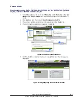
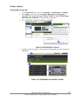
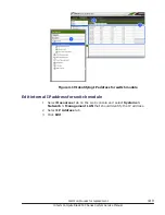

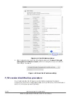
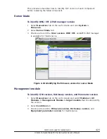
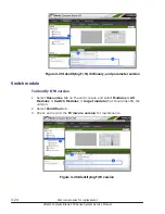
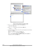

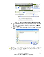
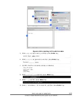

Confirming switch mode of FC switch module
To confirm the switch mode
1
.
Click Start > Programs > Accessories > Communications >
HyperTerminal to boot up terminal software.
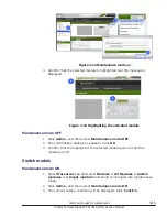
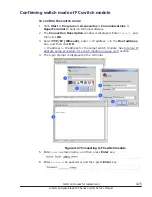
2
.
The Connection Description window is displayed. Enter
telnet1
, and
then click OK.
3
.
Select TCP/IP (Winsock), enter < IP address > in the Host address
box, and then click OK.
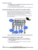
< IP address >:IP address for the target switch module. See
address setup procedure for switch module on page 4-18
section.
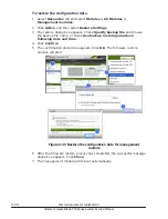
4
.
The login prompt is displayed in the terminal.
Figure 4-27 Connecting to FC switch module
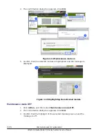
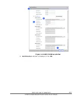
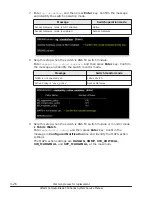
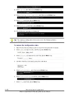
5
.
Enter
admin
as login name, and then press Enter key.
6
.
Enter
password
as password, and then press Enter key.
Common process for replacement
4-25
Hitachi Compute Blade 500 Series System Service Manual
Summary of Contents for CB 520A A1
Page 26: ...xxvi Preface Hitachi Compute Blade 500 Series System Service Manual ...
Page 152: ...4 64 Common process for replacement Hitachi Compute Blade 500 Series System Service Manual ...
Page 294: ...6 12 Identifying RAID rebuild status Hitachi Compute Blade 500 Series System Service Manual ...
Page 432: ...9 16 Updating firmware Hitachi Compute Blade 500 Series System Service Manual ...
Page 439: ...Change LOM configuration 10 7 Hitachi Compute Blade 500 Series System Service Manual ...
Page 442: ...10 10 Change LOM configuration Hitachi Compute Blade 500 Series System Service Manual ...
Page 450: ...10 18 Change LOM configuration Hitachi Compute Blade 500 Series System Service Manual ...
Page 464: ...11 14 Troubleshooting Hitachi Compute Blade 500 Series System Service Manual ...
Page 465: ...Hitachi Compute Blade 500 Series System Service Manual ...