A
F
F
E
B
D
A
A
B
B
C
C
A
Fig. 20a
1
3
2
2
Fig. 20b
Fig. 20c
1
4
2
2
3
3
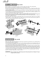
FENCE RAILS LOCKING LEVER (Fig. 20a)
The fence rails locking lever locks the rip fence in place preventing
movement during cutting.
• To lock the fence rails locking lever (A), push it up and toward the
front of the saw.
• To unlock the fence rails locking lever (A), push it down
and toward the rear of the saw.
NARROW FENCE (Fig. 20b)
Your table saw is equipped with a narrow fence (B) to support
workpiece that extends beyond the working table.
• To use the narrow fence (B), turn the locking lever (C) clockwise
and rotate the narrow fence (B) as shown in Fig. 20b, then turn
the locking lever (C) counter-clockwise to to lock.
• When not in use, turn the locking lever (C) clockwise and retracts
the narrow fence (B) as shown in Fig. 20b.
RIP FENCE (FIG. 20a-20c)
WARNING:
To reduce the risk of injury, always make sure the rip fence is parallel to the blade before beginning
any operation.
CAUTION:
When ripping, always lock the fence rails locking lever.
ADJUSTMENT KNOB (Fig. 20c)
The adjustment knob allows smaller adjustments when setting the
rip fence.
• Unlock the fence rails locking lever (A).
• Slide the rip fence (D) close to the desired position.
• Slowly turn the adjustment knob (E) to set the rip fence to desired
position. Turn the adustment knob clockwise will extend the fence
rails (F) to right. Turn the adjustment knob counter-clockwise will
extend the fence rails (F) to left.
• Lock the fence rails locking lever (A).
31
English


