The miter gauge (A) can be installed on each miter gauge groove (B) on either side of blade.
• Remove the miter gauge (A) from storage area (C) located on inside of the right side of saw).
• Slide the guide rail (D) of the miter gauge (A) into one of the guide grooves (B) of the saw table intended
for this purpose.
MITER GAUGE INSTALLATION (FIG. 12a-12b)
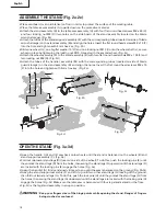
• The table saw has two convenient storage areas (one on either side of the saw) specifically designed for
the saw’s accessories: rip fence assembly (A), blade guard assembly (B), push stick (C), blade wrenches (D),
plug cable (E), anti-kickback pawls (F) and miter gauge (G).
• When not in use, store accessories securely.
TO STORE THE TABLE SAW ACCESSORIES (Fig. 13a-13c)
AA
0
8
1
9
2
10
24
32
23
31
22
30
25
33
26
34
27
35
CC
BB
2
3
2
1
1
Fig. 11c
Position screw BB: Begin with 8 in. to 35 in. end.
(Rip fence located on the right of the blade)
Position screw CC: Begin with 0 to 22 in. end. (Rip
fence located on the left of the blade)
Fig. 12a
Fig. 12b
A
A
A
B
C
C
D
A
A
D
E
A A
A
G
C
G
B
F
C
F
B
B
Fig. 13a
Fig. 13b
Fig. 13c
25
English
H
G
D
F
H B
C
B
A
1
C


