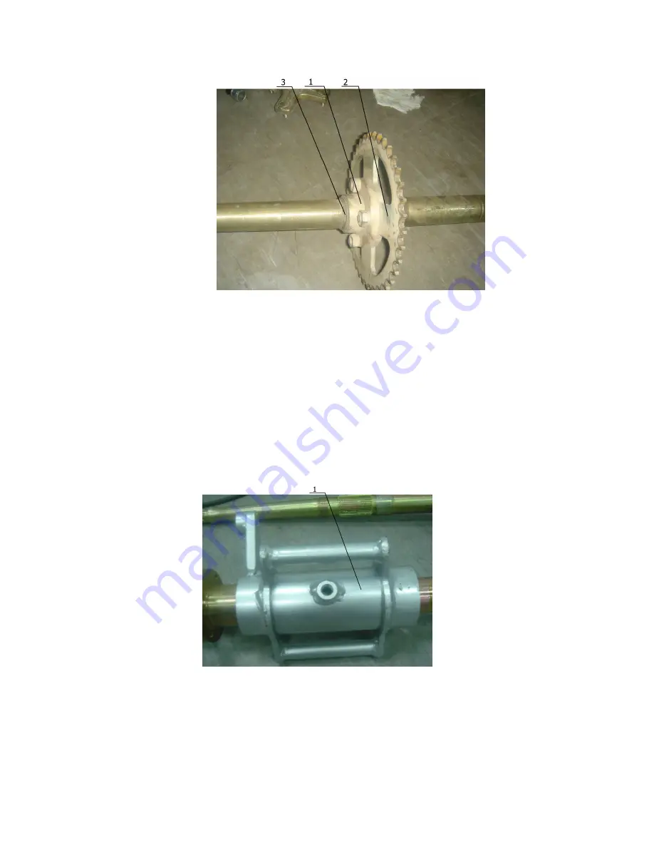
background image


71 


               Figure 4-4-9 

1.


Bottom Seat of Rear Sprocket 

2.


Sprocket    3、Circlip 

5、Mount Connecting Seat of Rear Bridge onto Rear Wheel 

Shaft from the right side and strengthen it by hitting 

with plastic hammer. (Figure 4-4-10) 


           Figure 4-4-10 

                     1. Connecting Seat of Rear Bridge 

6、Mount Bottom Seat of Rear Disk Brake Plate onto the Rear 

Summary of Contents for 450ATV-2

Page 1: ...450ATV 2 Maintenance Manual ...

Page 2: ...es 4 4 Transmission system 4 5 Reverse mechanism 4 6 Suspension 4 7 Cooling system of engine 4 8 Parking mechanism 4 9 Oil circulation System 4 10 Speed sensor Electrical system 5 1 Ignition system 5 2 Magneto and charging system 5 3 Battery 5 4 Lighting system 5 5 Meter and signal system 5 6 Starting system Appendix 6 1 Specification 6 2 Requirements for torque of fastener 6 3 Electrical circuits...

Page 3: ......

Page 4: ...1 1 Identification code 1 1 1 Frame No The frame No is engraved in the right bottom of the supporting frame See Figure 1 1 ...

Page 5: ...Figure 1 1 1 1 2 Engine No The engine No is engraved in the right side of the engine See figure 1 2 Figure 1 2 ...

Page 6: ...ght of various components 1 2 3 Vernier To measure the length of various components 1 2 4 Outside micrometer To accurately measure external diameter of a column 1 2 5 Inside micrometer To accurately measure internal diameter of a hole 1 2 6 Dial indicator To accurately measure a small distance 1 2 7 Torque Spanner To measure torque force ...

Page 7: ...ter of spark plug 1 3 Periodic maintenance chart for the emission control system NOTE For ATVs not equipped with an odometer or an hour meter follow the month maintenance intervals For ATVs equipped with an odometer or an hour meter follow the km mi or hours maintenance intervals However keep in mind that if the ATV isn t used for a long period of time the month maintenance intervals should be fol...

Page 8: ...f necessary Every 20 40 hours More often in wet or dusty areas Carburetor Check starter choke operation Adjust engine idling speed Crankcase breather system Check breather hose for cracks or damage Replace if necessary Exhaust system Check for leakage Tighten if necessary Replace gasket s if necessary Spark arrester Clean Fuel line Check fuel hose for cracks or damage Replace if necessary Engine o...

Page 9: ...steering shaft Lubricate every 6 months with lithium soap based grease Rear arm pivot Lubricate every 6 months with lithium soap based grease INITIAL EVERY Month 1 3 6 6 12 Km Mi 320 200 1 200 750 2 400 1 500 2 400 1 500 4 800 3 000 ITEM ROUTINE Whichever Comes first Hours 20 75 150 150 300 Fittings and fastener Check all chassis fittings and fasteners Correct if necessary Lights and a witches Che...

Page 10: ...10 4 1 Steering system Structure of Steering Vertical Column Components of Steering Bar ...

Page 11: ...11 4 1 1 Disassembly inspection and assembly of Steering System ...

Page 12: ...Column Steering Bar included 1 Remove the Front Faceplate and Meter Cover Figure 4 1 1 Figure 4 1 1 1 Front Mud Shield 2 Front Faceplate 3 Rear Mud Shield 4 Meter cover 2 Release the hexagon flange bolt M8 30 4pcs and remove the steering bar clip ...

Page 13: ...t Brake Lever and unplug all cables and connecting wires Figure 4 1 3 Figure 4 1 3 1 Throttle Cable 2 Connecting Wire 3 Clutch Cable 4 Brake fuel pipe 4 Front Brake Handlebar 6 Choke Cable 7 Parking Cable 4 Remove the cotter pin M14 open groove nut cushion and lower collar sheath at the bottom of the ...

Page 14: ...pen groove nut 2 4 cushionф14 ф32 4 3 Steering vertical column 4 cotter pin 3 2 32 5 Lower collar sheath 5 Release M8 32 Bolt 2pcs and remove the supporting brackets of the steering vertical column 4 6 Rotate the tension rod to detach it from the balance Figure 4 1 6 ...

Page 15: ...nts of the steering vertical column from the bottom seat Steering Vertical Column 2 Bottom Seat 4 1 1 2 Inspection of steering vertical column components 1 Check whether the hexagon open groove nut between the inner ball pin and tension rod is tightened ...

Page 16: ...t arm 4 Hexagon open groove nut 5 Ball pin In case of loosen or worn out tighten it with proper tools or replace with identical nuts Torque of the open groove nut 32 36N m 2 Check whether the inner and outter ball pin of the tension rod is loosen or got stuck ...

Page 17: ...ation must be carried out and replace with new ball pin components Caution Continuous use of defective ball pin might cause severe injury or death Additionally check whether the tension rod is bended cracked or rusted In occasion of above problems please have the tension rod replaced ...

Page 18: ...Open groove nut 2 Cushion 3 Steering vertical column 4 Cotter pin 3 2 32 5 collar sheath Those two components are crucial and should be replaced whenever there is a potential problem 4 Check whether the supporing bracket is firmly fixed to the steering vertical column Caution tension rod should not be repaired by welding ...

Page 19: ... to ensure the column is not stuck or swinging In occasion of above problems the supporting bracket must be replaced Rotating Torque of the steering vertical column 3 5N m 5 Check whether the bearing in the bottom seat is rotating smoothly and oil seals on both ends are not damaged Should there occurs any problem the bearing or oil seal must be replaced immediately 4 1 1 3 Assembly of steering ver...

Page 20: ... cotter pin 1pcs Fastening Torque of M14 open groove nut 80 85N m Caution before inserting the steering vertical column into the bottom seat both upper and lower oil seals must be greased with lithium lubrication 4 1 12 1 Hexagon open groove nut M14 1 5 2 Cushion 3 Steering vertical column 4 Cotter pin 3 2 32 5 Steering bottom seat 6 Lower collar sheath ...

Page 21: ... 1pcs and collar pipes 2pcs Fastening Torque of M8 60 Bolt 30 32Nm Caution inner surface of the supporting brackets must be greased with lithium lubrication 4 1 13 1 Stop reverse piece 2 Supporting stent 3 Steering vertical column 4 Inner and outer supporting bracket 1 Fix the tension rod into the conical bore of the steering vertical column with tension rod components ...

Page 22: ...3 2 32 2pcs Fastening Torque 28N m Figure 4 1 14 1 Turning shaft arms comp 2 Cushion ф10 3 Hexagon open groove nut M12 4 Cotter pin 3 2 32 4 1 2 Disassembly inspeciton and assembly of steering bar 4 1 2 1 Disassembly of steering bar 1 Remove the front faceplate and Meter Cover ...

Page 23: ...23 Figure 4 1 15 1 Front Mud Shield 2 Front Faceplate 3 Rear Mud Shield 4 Meter Cover 2 Remove steering bar clip 图4 1 16 Figure 4 1 16 1 Steering Bar Holder 2 Steering Bar ...

Page 24: ...1 17 2 Throttle Cable 2 Electrical wires 5 Clutch Cable 4 Fuel Pipe 6 Front Brake Handlebar 6 Choke Cable 7 Parking Cable 4 1 2 2 Inspection of steering bar 1 Check any existing or potential crack on the steering bar In case of above defects the steering bar must be replaced 2 Altitude balance on each end of the steering bar must ...

Page 25: ...cts on the fastening bolts in which case the bolts must be replaced 4 Check whether the steering bar clip is damaged 4 1 19 Radial runout and wear condition of the inner surface must be less than 0 8mm Otherwise replace the steering bar clip 4 1 2 3 Assembly of the steering bar 1 Connect the steering bar clip and holder with the Less than 3mm ...

Page 26: ... direction of brake cables on both left and right handlebar and clutch cable Figure 4 1 20 1 Steering bar holder 2 Steering bar 3 Steering bar cliop 4 Hexagon flange boltM8 30 Fastening Torque of the M8 30 Bolt is 26 30N m 4 2 Brake System Front Disk Brake components ...

Page 27: ...7 4 2 1 Preparation for inspection and maintenance of the front disk brake system 1 Brake system is crucial to the life safety of the operator and therefore must be periodically inspected and maintained ...

Page 28: ...ls under the minimum mark please refill the box with the same type of fluid as was recommended by the manufacturer Figure 4 2 1 to ensure the fluid level is higher than the minimum mark 4 2 1 1 Brake fluid box 2 Minimun mark b Travel distance of the front brake lever should be kept between 2mm 5mm Otherwise please adjust the screw to meet required travel distance ...

Page 29: ...ore periodical inspection of the fluid level is necessary Caution must use DOT4 Brake Fluid e Periodical inspection of the wear condition of front disk brake plate is also necessary Disk brake plate must be replaced depending on its wear condition The standard thickness of the disk is 4 0mm Caution 1 If the thickness of the disk brake plate is less than 3 5mm it must be replace 2 In occasion of cr...

Page 30: ...es hydraulic pressure of the brake fluid Therefore fuel pipe must be periodically inspected and replaced Inspection Method 1 Fuel pipe must be replace when worn out cracked or distorted 2 The life expectancy of the fuel pipe is 4 years and should be replaced in time 4 2 2 Disassembly inspection maintenance and assembly of Front Disk Brake System ...

Page 31: ...f front disk brake plate 1 Conical nuts M10 4pcs must be released before removing the wheel component Figure 4 2 4 Figure 4 2 4 1 Conical Nuts M10 2 Release M8 Bolt and remove the disk clip from the turning joint Figure 4 2 5 ...

Page 32: ...32 4 2 5 1 Brake plate clip 2 Front disk brake plate 3 M8 Bolt 3 Sequently remove the cotter pins open groove nuts cushion and front wheel hub from the front wheel shaft Figure 4 2 6 Figure 4 2 6 ...

Page 33: ...the disk brake plate from the front wheel hub Figure 4 2 7 Figure 4 2 7 1 Front disk brake plate 2 M8 Special Bolt 4 2 2 2 Disassembly of the Front Disk Brake Pump Handlebar included and Fuel Pipe 1 Release the M6 Bolts 2pcs of the Front Disk Brake Pump on the right of the Steering Bar Figure 4 2 8 ...

Page 34: ...ke Pump 2 Hexagon Bolt M6 2 Detach the Plate Clip from the Turning Joint 3 Remove the T Pipe from the frame Figure 4 2 9 Figure 4 2 9 1 Hexagon Bolt M6 2 T Pipe 4 Remove the Fuel Pipe Clip from the Lower Front Shaft Arm Figure 4 2 10 ...

Page 35: ... defects 2 Check Fastening Bolts of all Fuel Pipes for possible looseness or damage 3 Check all Fuel Pipes for deterioration distortion crack wear and other hidden defects 4 Check the Brake Plate Clip for distortion crack rust and stuck 5 Inspect the Brake Shoe for wear condition Brake shoe must be replaced when worn out Figure 4 2 11 Caution Brake shoe must be replaced when the thickness ...

Page 36: ...e replaced please refer to p 78 for maximum wear value of the Brake Shoe 4 2 2 4 Assembly of Front Brake System 1 Use Fuel Pipe Brackets 2pcs and Hexagon Flange Bolts M8 16 2pcs to connect the Fuel Pipe Clip with both left and right Lower Front Shaft Arms Caution Fuel Pipe must avoid physical contact with other components in movement ...

Page 37: ...2 12 1 Brake Fuel Pipe Clip 2 Fix the Disk Brake Plate onto the Front Wheel Hub with M8 Special Bolts 4pcs Figure 4 2 13 Figure 4 2 13 1 Disk Brake Plate 2 Bolt Caution grease the bolt with thread glue when ...

Page 38: ...nt Wheel Hub onto the Front Wheel Shaft with open groove nuts and cotter pins Figure 4 2 14 Figure 4 2 14 1 Open groove nut M14 2 Cotter pin3 2 32 3 Cushion 4 Fix the Plate Clip onto Front Turning Joint with M8 Bolts 2pcs Fastening Torque of Open groove nut 80N m 85N m ...

Page 39: ...Front Wheel Hub with M10 Conical Nuts 4pcs Figure 4 2 15 Figure 4 2 15 1 Conical Nut M10 Fastening Torque of Conical Nut 40N m 45N m 6 Fix Front Disk Brake Pump onto the Right Handlebar with M5 60 hexagon bolts 2pcs Figure 4 2 16 Fastening Torque of the bolt is 8N m 10N m ...

Page 40: ...the brake system Please apply the Brake Lever several times to fully engage the Disk Brake Plate and have the Brake Fluid circulating before riding the vehicle 2 After maintenance or replacement of a worn out Brake System make sure to adjust the newly assembled Brake System to meet the required performance level before returning it to the customer ...

Page 41: ...41 Rear Brake System Rear Brake System Rear Brake System Rear Brake System 4 2 3 Preparation for inspection and maintenance of the Rear ...

Page 42: ... plates mechanized by a rear brake pedal Please follow the tips of inspection as below g a Inspect the brake fluid box level on the right handlebar Should the fluid level falls under the minimum mark please refill the box with the same type of fluid as was recommended by the manufacturer Figure 4 2 17 to ensure the fluid level is higher than the minimum mark Figure 4 2 17 ...

Page 43: ...bar D Brake fluid will be automatically injected into the brake fuel pipe in the process of abrading brake pad reducing the fluid level in the box Therefore periodical inspection of the fluid level is necessary Caution must use DOT4 Brake Fluid E inspection of the wear condition of front disk brake plate is also necessary Disk brake plate must be replaced depending on its wear condition Figure 4 2...

Page 44: ...mm it must be replace 2 In occasion of crack or distortion the disk brake plate must be replaced h Disk brake plate uses hydraulic pressure of the brake fluid Therefore fuel pipe must be periodically inspected and replaced i Inspection Method 1 Fuel pipe must be replace when worn out cracked or distorted ...

Page 45: ...assembly Inspection and Assembly of Rear Disk Brake System 4 2 2 1 Disassembly of Rear Disk Brake System 1 Release M6 Bolt and detach Rear Disk Brake Pump from the Frame Figure 4 2 20 Figure4 2 20 1 Rear Disk Brake Pump 2 M6 Bolt 2 Remove Rear Disk Brake Box from the Frame Figure 4 2 21 4 2 21 ...

Page 46: ...rity Bolt and detach the Rear Disk Brake Clip Figure 4 2 22 Figure 4 2 22 1 Rear Disk Brake Clip 2 Bolt M18 14 4 Remove Rear Disk Brake System 4 2 4 2 Disassembly of Rear Disk Brake Plate 1 Release M10 Conical Nuts 4pcs and remove rear wheel components Figure 4 2 23 ...

Page 47: ... 4 2 23 1 Wheel Hub 2 M10 Conical Nuts 2 Sequently remove cotter pin M20 open groove nuts and cushion from the Rear Wheel Shaft then remove Rear Wheel Hub Figure 4 2 24 1 M20 Open groove Nuts 2 Cotter pin3 2 32 ...

Page 48: ...ng Nuts 2pcs from Rear Wheel Hub 4 2 25 1 Locking Nut M35 1 5 4 Remove the Bottom Seat of Rear Disk Brake Plate from the Rear Bridge Figure 4 2 26 Figure 4 2 26 1 Bottom Seat of Rear Disk Brake Plate 5 Release the Special Bolts 4pcs of the Rear Disk ...

Page 49: ...k the Brake Fluid Box for crack leakage and other potential defects 2 Check Fastening Bolts of all Fuel Pipes for possible looseness or damage 3 Check all Fuel Pipes for deterioration distortion crack wear and other hidden defects 4 Check the Brake Plate Clip for distortion crack rust and stuck 5 Inspect the Disk Brake Shoe for wear condition Brake shoe must be replaced when worn out Figure 4 2 28...

Page 50: ...ear distortion and crack in which case it must be replaced please refer to p 78 for maximum wear value of the Brake Shoe Maximum wear of Rear Disk Brake Plate is less than 3 5mm 4 2 2 4 Assembly of Rear Brake System 1 Fix Disk Brake Plate onto the Bottom Seat with Special M8 Bolts 4pcs Caution Grease the bolt with thread glue whenfastening ...

Page 51: ... M 24N M Figure 4 2 29 1 Rear Disk Brake Plate 2 Special Bolt M8 3 碟 Bottom Seat 2 Mount the Bottom Seat of Rear Disk Brake Plate onto Rear Bridge 3 Lock Rear Disk Brake Plate with M35 1 Bolts 2pcs Figure 4 2 31 Locking Torque 240N M ...

Page 52: ...52 Figure 4 2 31 1 Bottom Seat of Rear Disk Brake Plate 4 Mount the Disk Brake Clip onto Rear Bridge with M10 30 Bolts 2pcs Figure 4 2 32 Fastening Torque 18 Nm 22 Nm Figure 4 2 32 1 M10 30 Bolt ...

Page 53: ...ke onto the Frame with M6 Bolt 1pcs Figure 4 2 33 Fastening Torque 8N m 12N m Figure 4 2 33 1 Fluid Box of Rear Disk Brake 2 M6 Bolt 6 Mount Rear Disk Brake Pump onto the Frame with M6 Bolts 2pcs Figure 4 2 34 Fastening Torque 12N m 16N m ...

Page 54: ...e the Disk Brake Plate and have the Brake Fluid circulating before riding the vehicle 2 After maintenance or replacement of a worn out Brake System make sure to adjust the newly assembled Brake System to meet the required performance level before returning it to the customer 4 3 Wheel and Tyre 4 3 1 Preparation for maintenance of wheel 1 Inspect wear condition of the tyre Figure 4 3 1 ...

Page 55: ...e Wheel Hub is rusted or cracked 4 Check if the conical nuts of the Wheel Hub are loosen or distorted 4 3 2 Disassembly inspection and assembly of wheel components 4 3 2 1 Disassembly of wheel components Remove M10 Conical Nuts 4pcs and detach the tyre Figure 4 3 2 Figure 4 3 2 ...

Page 56: ...n of the tyre and wheel hub If the joint of tyre and wheel hub is loose replace the tyre immediately 4 Check the vibration of tyre wheel hub Vibration of assembled Tyre must be controlled within 3mm Otherwise please replace with new tyre Remove the tyre for vibration test of the wheel hub Should the vibration exceed 1 2mm the wheel hub must be replaced 5 Inspect the four conical bores on the wheel...

Page 57: ... shown as the arrow Front and Rear Wheels are not interchangeable Figure 4 3 3 Figure 4 3 3 1 Conical Nut M10 4 3 2 Speicification and operation guide of Wheel Hub and Tyre Since wheels and tyres are crucial to the vehicle operation periodical inspection for tyre pressure and profile depth is necessary Specification of Wheel and Tyre ...

Page 58: ...the course of operating the vehicle such as hard turning Excessive tyre pressure can also reduce the friction force between the tyre and ground causing spinning or lose of control Therefore please ensure the tyre pressure strictly complies with figures shown in the chart above Before operating the vehicle each time please check if profile depth of the tyre is over worn which might result in spinni...

Page 59: ...59 1 Height no less than 3mm 2 profile depth Figure 4 3 4 4 4 Transmission System Rear Bridge ...

Page 60: ...60 4 4 1 Disassembly inspection assembly of Rear Bridge components 4 4 1 1 Preparation for disassembly and maintenance of Rear ...

Page 61: ...al defects the wheel hub must be replaced immediately 2 Check if there exists any slip thread on the M20 open groove nut which is used to fasten the rear wheel hub 4 4 1 2 Disassembly of Rear Bridge 1 Release the M10 conical nut and remove the rear wheel Figure 4 4 1 Figure 4 4 1 1 M10 Conical Nut 3 Sequently remove cotter pin open groove nut cushion and rear wheel hub Figure 4 4 2 ...

Page 62: ...Cushion 4 Rear wheel hub 4 Detach the Chain 1 Inspection of Driving Chain Length of Driving Chain Maximum length of the driving chain is121 9mm Over the maximum length replace the three components of driving china driven sprocket and driving sprocket ...

Page 63: ...ure water or neutral abluent Completely grease the chain with ME 1 Sealed Chain Lubrication or SAE30 50 Engine Lubrication after cleaning Caution Do NOT use steam petrol or other volatile liquid Do NOT use other lubrication spray from the market ...

Page 64: ...64 3 Assembly of Driving Chain 1 Assemble the following components Chain connection components Connecting plate Connecting clip 5 Remove the bolts that connect Rear Bridge and Pan fork Figure 4 4 3 ...

Page 65: ...tach Rear Bridge from Pan fork Figure 4 4 3 7 Release M35 1 5 Bolts 2pcs and sequently remove from the right side Bottom Seat of Rear Disk Brake Plate and Connecting Seat of Rear Bridge Then take out the Rear Sprocket Seat from the left side after removing the Circlip Figure 4 4 4 ...

Page 66: ...f Rear Disk Brake Plate 3 Bearing Seat of Rear Bridge 4 Circlip 5 Bottom Seat of Sprocket 4 4 1 3 Inspection of Rear Bridge Components 1 Check if the splines of Rear Wheel Axle is damaged in which case Rear Wheel Axle must be replaced Figure 4 4 5 ...

Page 67: ...ion of the chain and replace when necessary 3 Remove the Chain 1 Inspection of Driving Chain Length of Driving Chain Maximum length of Driving Chain 121 9mm Over maximum length Replace the Driving Chain Driven Chain and Driving Sprocket ...

Page 68: ... Check if the Oil Seal in the Connecting Seat of Rear Bridge is deteriorated or distorted in which case the Oil Seal must be replaced 7 Check if Sprocket and Sprocket Spline are seriously distorted or worn out in which case they must be replaced immediately 8 Check if Rear Disk Brake Plate is seriously distorted or abraded in which case it must be replaced 9 Check if there exists any crack or dist...

Page 69: ...Rear Bridge 1 Mount the Sprocket onto Sprocket Bottom Seat with Bolts 4pcs Figure 4 4 6 Figure 4 4 6 1 Speical Bolt 2 Sprocket Bottom Seat 2 Mount Rear Disk Brake Plate onto the Bottom Seat of Disk Brake Plate with Special Bolts 4pcs Figure 4 4 7 ...

Page 70: ...ress the new Oil Seal into the Bottom Seat of Rear Bridge Bearing and grease it with lithium lubrication Figure 4 4 8 Figure 4 4 8 1 Oil Seal 2 Rear Bridge 4 Mount the Bottom Seat of Rear Sprocket onto Rear Wheel Shaft from the left side and affix it with circlip Figure 4 4 9 ...

Page 71: ...3 Circlip 5 Mount Connecting Seat of Rear Bridge onto Rear Wheel Shaft from the right side and strengthen it by hitting with plastic hammer Figure 4 4 10 Figure 4 4 10 1 Connecting Seat of Rear Bridge 6 Mount Bottom Seat of Rear Disk Brake Plate onto the Rear ...

Page 72: ...it with M35 1 5 Locking Nut Figure 4 4 11 Figure 4 4 11 1 Disk Brake Plate 2 M35 1 5 Nut 7 Fix Rear Wheel Hub onto Rear Wheel Axle with cushion M20 open groove nut and cotter pin Figure 4 4 12 Figure 4 4 12 1 M20 Open groove Nut ...

Page 73: ...on 4 Rear Wheel Hub 8 Connect the assembled Rear Bridge onto Pan fork with M10 Bolt Figure 4 4 13 Figure 4 4 13 1 Hexagon Flange Bolt M10 2 Rear Bridge 3 Pan fork 9 Mount the wheel onto Rear Bridge Figure 4 4 14 Figure 4 4 14 ...

Page 74: ...the Chain Figure 4 4 15 Figure 4 4 15 1 Chain 4 5 4 5 4 5 4 5 Inspection and Maintenance of Reverse Mechanism Inspection and Maintenance of Reverse Mechanism Inspection and Maintenance of Reverse Mechanism Inspection and Maintenance of Reverse Mechanism ...

Page 75: ...ck the mobility of Reverse Switch If it is not working properly remove the Reverse Device to check if the Reverse Cable is stuck Replace the Reverse Device lack of mobility 2 Check the mobility of Reverse Cable If it is not working properly replace with a New Reverse Cable 4 6 Suspension Front Suspension ...

Page 76: ...76 Pan Fork ...

Page 77: ...77 4 6 1 Disassembly Maintenace and Assembly of Front Suspension ...

Page 78: ...0 Bolt of Supporting Ring and remove the Front Suspension Figure 4 6 1 Figure 4 6 1 1 Hexagon Flange Bolt M10 2 Remove the cotter pin located on the ball pin of the Tension Rod M10 Open groove Nut Then pull out the Ball Head Figure 4 6 2 Figure 4 6 2 1 Ball Pin ...

Page 79: ...ning Joint 3 Remove the cotter pin and M10 Open groove Nut located on the Ball Head Figure 4 6 3 1 Cotter Pin 3 2 32 2 M10 Open groove Nut 4 Release the security bolt of Shaft Arm and remove them from both Front Upper and Lower Shaft Arms Figure 4 6 4 ...

Page 80: ...4 6 1 2Inspection and Maintenance of front suspension components 1 Inspection of Ball Head If the Ball Head is loose replace corresponding upper or lower shaft arm Figure 4 6 5 Figure 4 6 5 1 Ball Pin If Rubber Sheath of the Ball Pin is worn out or cracked plesae have it replaced immediately ...

Page 81: ... Figure 4 6 7 1 Conical surface of B all Pin 2 Turning Joint Check if the bolt of pin head is bended or have slip thread in which case the corresponding shaft arm must be replaced 2 Check the Upper and Lower Shaft Arm Inspect for distorting and rust In case of slight distortion try to repair by calibration However further inspection is necessary after calibration If cracks still exist please ...

Page 82: ...Nylon Bush must seamlessly match the liner pipe of the Shaft Arm If found loosen the nylon bush must be replaced Figure 4 6 8 Figure 4 6 8 1 Liner Pipe 2 Nylon Bush Liner Pipe must seamlessly fit into the Nylon Bush In case of looseness please replace with new nylon bush If rusted the liner pipe must be replaced 4 Inspeciton of Turning Joint Check if the Front Wheel Shaft in connection with ...

Page 83: ...igure 4 6 9 Figure 4 6 9 1 Front Wheel Shaft Inspect for any crack on the Turning Joint in which case it must be replaced 5 Inspection of Front Suspension Bending of the suspension Spring must be less than 2mm Otherwise plesae replace with new suspension Figure 4 6 10 ...

Page 84: ...degrade over time in which case it must be adjusted with special tools Figure 4 6 11 Figure 4 6 11 Check if there exists any crack on the suspension in which case it must be replaced Caustion Both suspensions must be replaced simultaneously 4 6 1 3 Assembly of Front Suspension ...

Page 85: ...n bush and collar pipe then press nylon bush into liner pipe and fill up collar pipe with lithium lubrication 3 Fix Shaft Arm onto the Frame with M10 Bolt Figure 4 6 12 Figure 4 6 12 1 Front Upper Shaft Arm 2 Front Lower Shaft Arm 4 Mount Turning Joint onto Shaft Arm with M10 Open groove Nut 5 Fix Tension Rod onto Turning Joint with M10 Open groove ...

Page 86: ... Figure 4 6 14 Figure 4 6 14 1 Cotter Pin 2 Open groove Nut 3 Turning Joint 4 Head Pin of Tension Rod 6 Mount the Suspension onto the Frame and Lower Shaft Arm with M10 Bolt Figure 4 6 15 Fastening Torque of M10 Nut 40 45Nm ...

Page 87: ...dge from Pan Fork Refer to Page 1 3 Disassembly of Rear Bridge 2 Release the M12 Bolt of both Upper and Lower Supporting Brackets of Rear Suspension and take out the Suspension Figure 4 6 16 Figure 4 6 16 1 M12 Bolt 2 Rear Suspension 3 Release the M12 Bolt between Shaft Arm of Rear Suspension and Pan Fork then take off the Shaft Arm Figure 4 6 17 ...

Page 88: ...elease the M14 Nut of Pan Fork Shaft take out the Shaft then finish the disassembly process of Rear Suspension Figure 4 6 18 Figure 4 6 18 1 M14 Nut 4 6 2 2 Inspection and Maintenance of Rear Suspension 1 Inspection of Pan Fork Check if there exists any severe distortion on the ...

Page 89: ...rk must be replaced Welding must be done by qualified technician when necessary Check if the Needle Bearing of the Liner Pipe is damaged in which case the Needle Bearing must be replaced Figure 4 6 19 Figure 4 6 19 1 Pan Fork 2 Needle Bearing 2 Inspection of Pan Fork Shaft Arm Check if there exists any distortion or crack on the Pan Fork Shaft Arm in which case it must be replaced Inspect wear con...

Page 90: ...nd Liner Pipe of Rear Suspension Shaft Arm with soft cloth grease Needle Bearing with Lithium Lubrication and place Liner Pipe into Needle Bearings 3 Mount Pan Fork onto the Frame with Pan Fork Shaft 4 Use Special Pin and Cotter Pin to have Rear Suspension and Shaft Arm connected 5 Use M12 Bolt to connect Shaft Arm with the Frame and Pan Fork 6 Use M12 Bolt to mount the upper end of Rear Suspensio...

Page 91: ...col antifreeze containing corrosion inhibitors for aluminum engines Antifreeze and water mixing ratio 1 1 Total amount 1 8L 1 58 lmp qt 1 90 US qt Coolant reservoir capacity up to the maximum level mark 0 3L 0 26lmp qt 0 32 US qt 4 7 1 1 Disassembly of Water Cooling System 1 Detach Front Mud Shield and Front Faceplate Figure 4 7 1 Figure 4 7 1 ...

Page 92: ...he bolt under Fluid Tank and take off the Fluid Tank Figure 4 7 2 2 Figure 4 7 2 1 Fluid Tank 2 M6 Bolt Caution Do NOT spoil cooling fluid onto the Frame 3 Detach the rubber inlet pipe on the left side of the Frame to drain out the fluid Figure 4 7 3 1 ...

Page 93: ...f Water Cooling System is torn or worn out If so please replace with new pipe 2 Check the tightness of the hoop on the rubber pipe connected with Water Cooling System If loosen please have the hoop tightened immediately 3 Inspect if Cooling Fan is damaged If so please replace with new Cooling Fan 4 7 1 3 Assembly of Water Cooling System ...

Page 94: ... with Engine 3 Mount Fluid Tank onto the Frame and connect Communicating Pipe with Overflow Pipe using M6 Bolts 4 Fill in 5 5 Cooling Fluid 5 Start engine inspect fluid level fulfill Fluid Tank and close the cap 4 7 2 Disassembly Inspection and Assembly of Oil Pot Oil Cooling System 4 7 2 1 Disassembly of Oil Pot 1 Release the Oil discharge Bolt to drain out the oil from engine Figure 4 7 4 Figure...

Page 95: ...ease M6 Bolt and take off the Wind Guide Cover Figure 4 7 5 Figure 4 7 5 1 Wind Guide Cover 2 Oil Pot 3 Oil Gauge 3 Release the M6 Bolts on both inlet and outlet pipes of the engine and take out the two steel pipes Figure 4 7 6 1 2 ...

Page 96: ...96 Figure 4 7 6 1 Steel Pipe 1 2 Steel Pipe 2 4 Release the Hoop and take off the rubber pipe connected with engine 1 2 3 Figure 4 7 7 1 Rubber Pipe 1 2 Rubber Pipe 2 3 Hoop ...

Page 97: ...oop on Rubber Pipe is loosen Replace loosen hoop 4 Clean Oil Pot after inspection 4 7 2 3 Assembly of Oil Pot 1 Connect Rubber Pipe to Oil Pot with the hoop 2 Connect inlet and outlet steel pipes to engine with M6 Bolt 3 Connect the third rubber pipe to the oil pipe fitting located at the end of engine and fasten with a hoop 4 Tighten the Oil discharge Bolt of engine 5 Pour 2 8L SAE10W 40 Engine O...

Page 98: ...ff Stop Lever from Left Handle Bar Figure 4 8 1 Figure 4 8 1 1 Stop Lever 2 Take off Stop Cables from Rear Bridge Figure 4 8 2 Figure 4 8 2 1 Stop Cable 2 Parking Device 3 Release M8 Hexagon Bolt and take off Braking Mechanism Figure ...

Page 99: ...e defective Stop Cables 3 Check the mobility of Parking Mechanism and replace defective components 4 8 3 Assembly of Parking Mechanism 1 Grease Parking Mechanism with Lithium Lubrication and mount it onto Rear Brake Plate Clip with M8 Bolts 2pcs 2 Assemble Stop Cables 3 Mount Stop Lever onto the left side of Steering Bar Qualified Parking Mechanism must ensure the vehicle ...

Page 100: ...buretor 5 Negative Pressure Pump 1 Check for Fuel Tank Clogging 2 Check if Fuel Filter is clogged 3 Check if the pipe connecting Fuel Filter with Negative Pressure Pump has air leakage 4 10 Inspection and Assembly of Speed Sensor 4 10 1 Inspection of Speed Sensor 1 Check if Speed Sensor located on Rear Bridge is loose 2Check if there exists any pollutant inside Speed Sensor ...

Page 101: ...19 Blue Black L B 3 Yellow Y 20 Red Black R B 4 Green G 21 Red White R W 5 Orange O 22 Green White G W 6 White W 23 Brown White Br W 7 Gray Gr 24 Brown Blue Br L 8 Blue L 25 Red Brown R Br 9 Brown Br 26 Yellow Red Y R 10 Dark Green Dg 27 Green Red G R 11 Dark Red Dr 28 Green Black G B 12 White Green W G 29 Black White B W 13 White Red W R 30 White Blue W L 14 White Black W B 31 Yellow White Y W 15...

Page 102: ...he safety whether the safety is good or not 2 Second if the safety is good then check the battery whether it is power on 3 Finally check the switch lock and electric route whether they are bad Other troubleshooting and causations as follows ...

Page 103: ...y or short circuit repair repair replace repalce repalce repalce 2 spark weak or sparkover intermittence 1 spark plug pollute or wear intermittence 2 high voltage bag high voltage lead wire insulated badness repalce replace electrification system 1 discharge self 2 uncharge or shortage charge 1 cover polluted or drenched by rain 1 carve out a way or short circuit caused by connected wire badness 2...

Page 104: ... carve out a way or short circuit 1 horn septum damaged connector not ordered adjusted bolt not ordered 1 routing wire carve out a way or short circuit 2 lamp filament damaged 3 switch the switch of lighting damaged or contacted badness 1 the switch of brake the nut of swith are not ordered two contact touched badness 2 lamp filament of lamp repair or replace replace replace repair or repalce repa...

Page 105: ...105 damaged 3 routing wire carve out a way or short circuit replace replace or repair 5 ignition system ...

Page 106: ...ng coil produce spring signal provided to SCR as the turnon spring signal when reaching the ignition timing SCR turnon capacitance began to discharge at the elementary coil L1 caused instant lower pressure while at the secondary coil caused induce pressure its instant pressure up to 10000V sparkover at the clearance of sparkplug 0 6mm so the engine ignited charge system The chart of charge element...

Page 107: ...hange the battery 1 With long time charge but the pressure do not increase to a set value 2 At the bottom of case there is something dirty or electrode have become white or the case with a sulfate function 3 Electrode former scratched or scratched by press or insulation without work Pay attention when using 1 Long time out of using but without charge is not correct 2 Too much charge so long time c...

Page 108: ...cigarette When charge or using in house keep the air easy floating When work near the battery please take care of your eyes and keep kids away from the battery If under such accidents please deal with it as follows or ask for help from the doctors 1 Exterior wash lots of cleaning water 2 Interior drink milk or water and then milk of magnesia or egg or rap oil and hospitalize as soon as possible 3 ...

Page 109: ...s red do not shine 总保险盒 红2 红 白 绿 白 灯 指示 转向 左右 黑 棕 灰 墨绿 深棕 绿黑绿红 黄 墨绿 深棕 蓝绿红 OFF OFF OFF 开关 应急 开关 转向 开关 喇叭 白 白 白 整流器 磁电机 开关 熄火 开关 电起动 关 动开 前制 关 动开 后制 12V 3W 黑 仪表指示灯 深棕 深棕 墨绿 墨绿 钮 按 动 起 电 尾灯 制动灯 前大灯2 黑 12V 10W 黑 黑 黑 12V 5W 21W 12V 18W 向灯 右转 前左 向灯 右转 后左 紫 前大灯1 开关 控制 油温 油温指示灯 黑 12V 1 7W 黑 12V 18W 黄 绿 黄2 蓝 绿 黄 黄绿 黄 绿 红1 黑 15A B M M 兰 白 棕 黄 红 棕 兰 红 棕 红 白 红 兰 黑1 25A 大灯 5A 二 四驱 25A 点火 10A 信号指示 电门锁 功能红1棕 兰 ...

Page 110: ... guide 5 6 Starting system Starting Circuit Starting system working process Turn on the start switch on the left handlebar the battery can supply power for the CDI Then the CDI supply power for the startor relay then the power from the battery can be sent to the startor motor through the startor relay and the startor motor works help the engine to work 功能 浅绿 黄红 ...

Page 111: ...arge enough 2 When starting if heard some noises from the startor relay the battery must be without enough power Please stop starting and change a powerful battery or charge for it 3 If the startor motor can not work normally please check according to the 2 rule to see if it is not lubricated enough Appendix 6 1 Specification 6 1 1 Table of specification a Specification of vehicle Overall length 2...

Page 112: ...ot right hand operation Primary Brake 2 Front dual disk Rear single disk front and rear linkage right foot right hand operation Emergency brake 刹中轴 L hand operation Parking brake Engine hand operation Gear shift handle Front Alloy Steel wheels Wheel Hub Rear Alloy Steel wheels Front 25x8 12 Vacuum Tyre Tyre dimension Rear 25x10 12 Vacuum Tyre Front 35kpa Tyre pressure Rear 35kpa Fuel tank Vol 17L ...

Page 113: ...3kW 5500r min Rated power 24kW 6000r min 6500r min Max Torque 49N m 5000r min Max Torque E mark 27 5N m 4500r min Mini Idle speed 1400 100r min Fuel type Unlead 90 Lubrication Pressure Splash Starting system Electric Start and hand recoil start Ignition C D I Drive train Axle Transmission CVT Belt drive ratio 5 0695 0 7679 L Drive ratio 5 3595 30 17 41 21 24 18 H Drive ratio 3 2230 26 21 41 21 24 ...

Page 114: ...L Engine dry weight 71kg c Components Specification Carburetor PD42J Pattern Parallel Vacuum Spark plug DR8EA Speed meter Electronic Battery 12V 21Ah Headlight 12V 35W 35W White light Front Indicator 12V 3W White light Rear Indicator 12V 5W Red light Brake light 12V 21W 12V 21W 12V 21W 12V 21W Red light Rear license plate light 12V 5W White light Turning light 12V 10W Amber light Rear reflector Re...

Page 115: ...e Magneto Rotate DC output Spark plug gap 0 6 0 7 mm Safety fuse 30A CDI L2 L1 OVERRIDE 本电路特点 1 在N 驻车 刹车时能实现电起动 2 在R档位时 发动机R档开关接地 通过CDI内部晶闸管控制而使仪表空档灯接地 才使R档灯亮 3 二极管在此电路中作用在于 在后制动 驻车时能实行电起动 4 继电器电源 通过CDI工作才能给其供电 这样能起到保护继电器的作用 延长其使用寿命 5 采用总保险盒的形式 各工作电路独立 方便检修 且电缆总成内部同功能线无接头 不容易在 电缆内部形成虚接现象 30A 34100 058 0000 HS700ATV 电气原理图 审 核 批 准 更改文件号 标记 设 计 标准检查 处数 签字 日期 重庆环松工业 集团 有限公司 34100 058 00 比例 第 页 图样标记 所属...

Reviews: