


5.1 Installation guidelines
17
5 Installation
Version 1.0 03/06
5 Installation
Interference suppression of switched inductances
䊳
Suppressing switched inductances with fuses
Switching inductances, e.g. in relays and fans, gener-
ates interference voltages which are many times
higher than the switched operating voltages.
These interference voltages might affect electronic
appliances.
The interference voltages of inductances must be
limited at their source of emission by means of fuses
(by connecting diodes or RC elements). Only use
interference suppressors which are intended for the
relays and fans used.
D
Cabinet lighting
Use filament lamps (e.g. LINESTRA lamps) for the
cabinet lighting. Do not use fluorescent lamps be-
cause they generate interference fields. If the use of
fluorescent lamps cannot be avoided, the interference
suppression measures shown in Fig. 7 must be imple-
mented.
Electromagnetic compatibility (EMC)
Electromagnetic compatibility (EMC) covers all aspects
regarding the effects of radiated and received electrical,
magnetic and electromagnetic emissions.
In order to prevent interference in electrical systems,
these effects must be reduced to a minimum.
The structural design and correct connection of bus lines
as well as the interference suppression of switched induct-
ances play a major role in limiting interference.
5.1 Installation guidelines
Shield grid
over lamp
Shielded cable
Metal-encased
switch
Mains filter or
shielded mains cable
Fig. 7: Interference suppression of fluorescent lamps
in cabinet
Arrangement of devices and cables
D
Reducing interference by providing adequate space
A simple yet effective way of reducing interference is
to separate devices and cables causing interference
from those affected by interference. Inductive and
capacitive interference injection decreases by the
square of the distance between the elements
concerned. This means that doubling the distance
reduces the interference by a factor of 4. If the
arrangement of the various elements in a building or
in the switch cabinet is taken into consideration at the
planning stage, the cost of the necessary interference
suppression measures is generally very low.
䡲
䊳
Please note:
Between an OZD 485 G12 BAS and a power switching
element (e.g. contractor, relay, temperature regulator,
switch, etc.) a minimum separation of 15 cm is to be
maintained.
This minimum is to be measured between the outer
edges of the components and in all directions around
ann OZD 485 G12 BAS.
Summary of Contents for 943 893-321
Page 6: ...4 Version 1 0 03 06...
Page 8: ...6 Version 1 0 03 06...
Page 12: ...2 Half duplex operation 10 Version 1 0 03 06...
Page 14: ...3 Tristate recognition through permanent highHigh 12 Version 1 0 03 06...
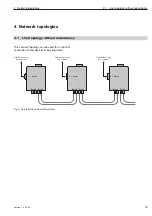
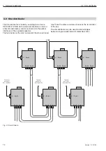
Page 18: ...4 Network topologies Subkapitel 16 Version 1 0 03 06...
Page 26: ...5 Installation 24 Version 1 0 03 06...
Page 32: ...7 Help with problems 30 Version 1 0 03 06...
Page 35: ......


