Operating Procedures 7
SHORT SPINNER OPERATION
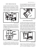
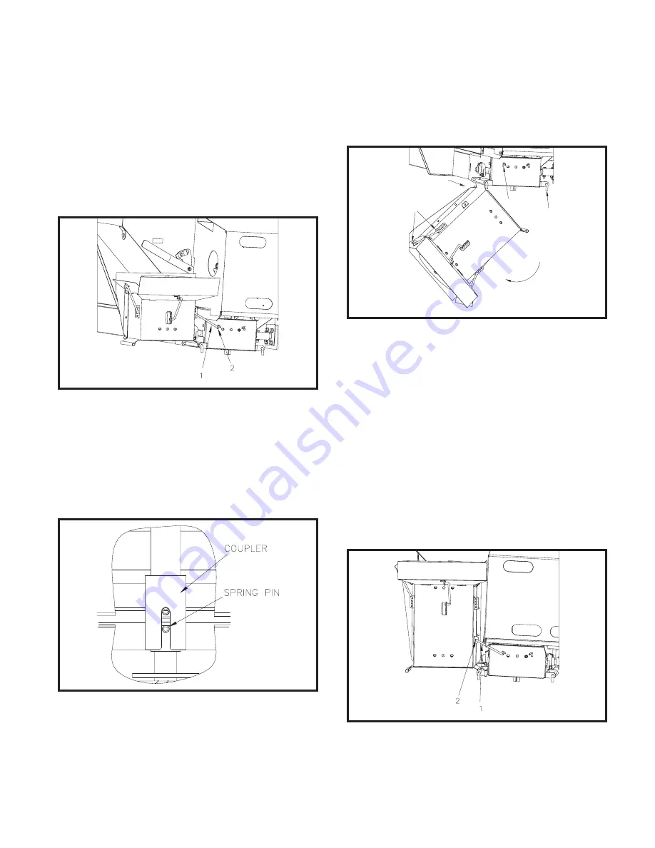
To utilize this option pull the pin at location 1
and allow the chute to swing open. This disen-
gages the spinner from the spreader. The spin-
ner may need to be rotated slightly to fully dis-
engage the spinner. Slide the chute rearward
about 1 1/2 inches. Pull the hair pin cotter at
location 2. Disengage the deflector pin from the
hole in the deflector
DWG. NO. 6022
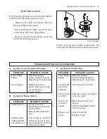
Rotate the chute assembly approximately 180
degrees. Insert the pin (arrow 1) from the exter-
nal deflector into the hole of the top chute mount
at location 2. Insert the hair pin cotter into the
pin behind the top chute mount to secure the
chute in this position.
DWG. NO. 6023
To realign the shafts for spreading, reverse the
above steps. When the chute has been secured
to the spreader, check that the coupler has fully
engaged the spring pin on the spinner shaft.
If it is not engaged turn the spinner shaft until
the spring pushes the coupler over the spinner
shaft and the coupler engages the spring pin.
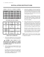
A fully engaged spinner will look like the above
drawing.
SLIDE REARWARD
2
3
1
DWG. NO. 6024
LONG SPINNER OPERATION
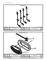
To utilize this option pull the pin at location 1 and
allow the chute to swing open. This disengages
the spinner from the spreader. The spinner may
need to be rotated slightly to fully disengage the
spinner. Slide the chute rearward about 1 1/2
inches. Pull the (2) hair pin cotters at location 2.
Remove the left deflector pin from the chute as-
sembly. Insert one end of the pin into the hole in
the top chute mount at location 3. Insert the hair
pin cotter into the pin hole behind the top chute
mount to secure the pin in position.
DWG. NO. 6025
Rotate the chute assembly approximately 180
degrees. Insert the other end of the pin (arrow
1) from the external deflector into the formed
tab of the spinner assembly at location 2.


