10 Maintenance & Service Procedures
CHAIN TENSION
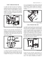
Tighten the conveyor chain periodically to com-
pensate for the chain stretching. Adjust both
sides the same amount to equalize the load on
the chain.
DWG. NO. 6026
Loosen the front nut, then turn the adjustment
bolt to take up the slack.
DWG. NO. 6596
Retighten the front nut after the chain is adjust-
ed. A properly tensioned chain can be pulled up
2-3 inches about 24 inches from the back of the
spreader side rails. A chain that is too tight will
cause excess stress on drive components.
DWG. NO. 6027
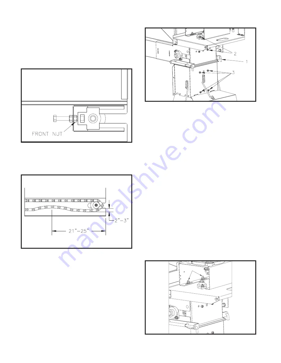
To adjust tension in the roller chain between the
gearbox and the spinner shaft first pull the pin at
location 1 and allow the spinner to swing open.
Loosen the (4) nuts, at location 2, that secure
the upper bearings which hold the upper spin-
ner shaft. Slide the top spinner shaft away from
the gearbox to tighten the chain. Make sure the
shaft is vertical before retightening the hard-
ware.
Rotate the chute assembly and reinsert the pin
at location 1. Loosen the (4) nuts, at location 3,
that secure the bearings which hold the bottom
spinner shaft. Slide the bottom shaft until it is
aligned with the top shaft.
When the shafts are aligned, the coupler on the
upper shaft will slide over the bottom shaft and
the spring pin will engage the slot in the cou-
pler. The bottom shaft may need to be rotated
slightly to align the slot in the coupler with the
spring pin. Make sure the bottom shaft is verti-
cal before retightening all hardware.
1
DWG. NO. 6028


