background image

21

8. Applications

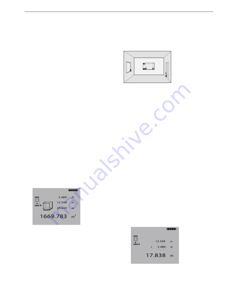
The individual steps for determining a 
volume are supported by a corresponding
graphic display. To determine the volume
of a room, for example, the following 
procedure must be followed:

1. At the start of the volume function, 

the laser beam is switched on. 

2. Aim the range meter towards at the 

target.

3. Press the "Measure" key.

The room width will be measured and 
shown.

4.  After this, the graphic display will 

automatically request measurement 
of the room length.

5.  Aim the range meter at the next target

to obtain the room length.

6. Press the "Measure" key.

The room length will be measured.

7. After this, the graphic display will 

automatically request measurement 
of the room height.

8. Aim the range meter at the next target

to obtain the room height.

9. Press the "Measure" key.

The room height will be measured, the
volume immediately calculated and 
the result shown in the result line.

All three distances required to calculate 
the volume appear in the intermediate
result lines and can be conveniently noted
after the measurements and the calculation.

- NOTE -

To determine another volume, press the
"Volume" function key  again until the 
graphic symbol for “Volume” appears.

8.4 Adding distances

Single distances can be conveniently added.
This is useful for determining door or 
window openings or to add several partial
distances to form the perimeter. 

1. Press the "Measure" key.

(The laser beam will be switched on).

2.  Direct the range meter towards 

the target.

3. Press the "Measure" key.

The first distance will be measured 
and shown.
(The laser will be switched off.)

4.  Press the "Plus" key to add the next dis-

tance. The first distance will appear in
the middle intermediate result line and
a plus sign in the lowest one.
(The laser beam will be switched on.)

5.  Aim the range meter at the next target.
6.  Press the "Measure" key.

The second distance will be measured
and shown in the bottom intermediate
result line. The calculation result will
appear in the result line at the same
time.

The current total of the distances is always
shown in the result line.

This procedure can be repeated until all
distances have been added.

To terminate the addition of distances, 
simply measure a distance without first 

MEN

x

+
-

I

=

PD 25

MEN

x

+
-

I

=

PD 25

MEN

x

+
-

I

=

PD 25

ME

N

x

+

-

I

=

PD 25

MEN

x

+

-

I

=

PD

 2
5

MEN

x

+
-

I

=

PD 25

Printed: 07.07.2013 | Doc-Nr: PUB / 5070013 / 000 / 00

Summary of Contents for PD 32

Page 1: ...282410 282410 pt Operating instructions 1 30 Mode d emploi 31 60 Istruzioni d uso 61 90 Manual de instru es 91 120 Manual de instrucciones 121 150 en fr es it Printed 07 07 2013 Doc Nr PUB 5070013 00...

Page 2: ...5 2 4 9 6 3 1 7 12 8 10 10 11 11 11 13 Printed 07 07 2013 Doc Nr PUB 5070013 000 00...

Page 3: ...PDAW 80 1 PDA 50 PDA 60 PDA 61 PDA 62 PDA 70 PDAW 80 81 3 PDAW 81 1 PDAW 80 81 2 PDAW 80 81 1 PDA 81 PDA 80 PUA 60 Printed 07 07 2013 Doc Nr PUB 5070013 000 00...

Page 4: ...tograms 3 1 3 Location of identification data on the range meter 3 2 Description 4 2 1 Intended use 4 2 2 Items supplied 4 2 3 Measuring principle 4 2 4 Range meter functions 4 2 4 1 General range met...

Page 5: ...s 18 7 4 8 Taking measurements to round or inclined surfaces 18 7 4 9 Taking measurements to wet or shiny surfaces 18 7 4 10 Taking measurements to transparent surfaces 19 7 4 11 Measuring ranges 19 8...

Page 6: ...the rating plate on the range meter Make a note of this data in your operating instructions and always refer to it when making an enquiry to your Hilti representative or service department Type Seria...

Page 7: ...1 Operating instructions 1 Producer Certificate 2 3 Measuring principle The range meter emits a visible laser beam with measuring waves which are reflected returning with a phase shift The phase shif...

Page 8: ...laser beam should be perpendicular to the target plate whenever possible If this not the case the laser spot on the target plate may not be in the same plane as the target point and the distance meas...

Page 9: ...plies current to the charging adaptor Prior to charging the battery the side flange connections should be carefully checked 3 6 PDAW 80 81 3 battery pack The battery pack consists of two rechargeable...

Page 10: ...5 mm 20 ppm 1 16 inch 20 ppm due to atmospheric conditions This affect is typically noticeable at distances 100 m 300 ft Smallest unit displayed 1 mm 1 16 inch Beam diameter 6mm 10m 0 2 in 30 ft 30mm...

Page 11: ...ty surrounded by areas with high reflectivity may lead to measurement errors Measurements taken through panes of glass or other objects may be inaccurate Rapid changes of the measuring conditions e g...

Page 12: ...e g aircraft navigational equipment The range meter might be subject to interference caused by powerful radia tion which can then lead to incorrect operation Check the readings for plausibility when m...

Page 13: ...teries are mostly empty and have to be charged prior to first use Use only NiMH batteries with 1 2 V and 1500 2000 mAh capacity 6 2 Battery charging 6 2 1 Standard charging of batteries The charging p...

Page 14: ...m the mains adaptor or by removing replace the rechargeable batteries Keep the range meter in a safe place 6 2 2 Fast battery charging The charging process ensures that within 15 minutes of charging w...

Page 15: ...ch2 inch3 in 1 8 feet inch 1 8 feet2 feet3 in1 16 feet inch 1 16 feet2 feet3 6 4 4 Terminating the menu The menu is terminated by pressing the On Off key All settings displayed will be saved Beep Unit...

Page 16: ...nction and deactivates every other function Area activates the area function and deactivates every other function Plus activates the distance addition function and deactivates every other function Min...

Page 17: ...0 m 50 inch to measurements Battery status 4 segments 100 full 3 segments 75 full 2 segments 50 full 1 segment 25 full 0 segments empty Batteries empty Action Replace batteries Re charge rechargeable...

Page 18: ...Press the Measure key or Side measure key keep aiming until the laser spot in the optical sight disappears Read the distance in the display Diagram of optical sight NOTE It is practical for the optic...

Page 19: ...his aiming mode as an animated dashed line 16 3 Aim to the target 4 Press the Measure key once again to measure the distance The result appears in the result line normally in less than a second The la...

Page 20: ...his depends on the reflectivity of the target surface If the beep signal is switched on continu ous measurement is indicated by a Beep The measuring process is stopped by pressing the Measure key once...

Page 21: ...PDA 50 target plate 7 4 7 Taking measurements to rough surfaces When measuring to rough surfaces e g coarse render stucco etc an average dis tance value is measured weighting the cen tre of laser spot...

Page 22: ...er objects in the target beam can lead to a reduced measuring range Taking measurements to matt green blue or black wet or shiny surfaces can lead to a reduced measuring range 8 Applications and calcu...

Page 23: ...ace of a room for example the following procedure must be followed a b a b 1 At the start of the area function the laser beam is switched on 2 Aim the range meter at the target 3 Press the Measure key...

Page 24: ...NOTE To determine another volume press the Volume function key again until the graphic symbol for Volume appears 8 4 Adding distances Single distances can be conveniently added This is useful for det...

Page 25: ...ion will appear in the result line The current difference between distances is always shown in the result line 8 7 9 5 4 6 2 1 3 0 C I PD 28 x 8 7 9 5 4 6 2 1 3 0 C I PD 28 x This procedure can be fol...

Page 26: ...e Indirect distance measurement function key once again switches to the simple version Pressing this key a third time switches from this function back to the normal display mode 10 10 10 8 6 3 Indirec...

Page 27: ...llel objects m ft 90 PD 22 MEN 1 x PD 22 MEN 1 x PD 22 MEN 1 x Both functions are activated simultaneously by pressing the Min Max key In addition the difference between minimum and maximum is shown 8...

Page 28: ...3 0 C I PD 28 x 8 7 9 5 4 6 2 1 3 0 C I PD 28 x 8 7 4 C PD 28 8 7 3 Combined measurement The combination of simultaneous display of maximum and minimum distances permits the calculation of offsets di...

Page 29: ...You may carry out the inspection measuring and test of the PD 32 laser range meter as specified in ISO 900X See ISO 17123 4 Field Process for Accuracy Examinations of Geodetic Instruments Part 6 Close...

Page 30: ...nies that have been certified according to ISO 900X Your local Hilti contact representative will be pleased to provide further information 10 Care and maintenance 10 1 Cleaning and drying Blow dust of...

Page 31: ...parately and returned to an environmentally compatible recycling facility 12 Manufacturer s warranty tools Hilti warrants that the tool supplied is free of defects in material and workmanship This war...

Page 32: ...ncouraged to try to correct the interference by one or more of the following measures Re orient or re locate the receiving antenna Increase the separation between the equipment and receiver Connect th...

Page 33: ...product complies with the following standards or standardization documents EN 50081 1 and EN 61000 6 2 according to the stipulations of the directive 89 336 EEC Hilti Corporation Matthias Gillner Head...

Page 34: ...111 Fax 423 2342965 www hilti com Hilti registered trademark of Hilti Corp Schaan W 2906 0306 20 Pos 1 1 Printed in Liechtenstein 2006 Right of technical and programme changes reserved S E O 282410 C...

Reviews: