26)
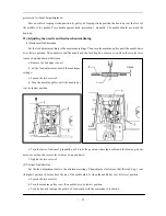
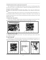
Adjusting the fixed knife position
The distance from the groove of slide plate to the fixed knife 1 should be 26 mm. Furthermore, the
le plate to the left edge of the tip of the fixed knife 1 should be 4 mm.
Loosen the two bolts 2.
) Adjust the position of the fixed knife 1, and then tighten the bolts 2.
7)
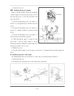
Adjusting the thread holding spring position (see the picture of above)
The thread holding spring 1 holds the lower thread after thread trimming to prepare it for the next sewing
peration. The clearance between the thread holding spring 1 and the side of the fixed knife 2 should be 1.4-1.6
m.
(1) Loosen the two screws 3.
(2) Move the thread holding spring 1 to adjust its
position, and then tighten the screws 3.
28)
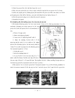
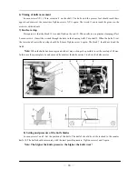
Adjusting the knife timing position
After adjusting the position of the fixed knife 1, adjust
the knife timing position.
Adjust so that the driving knife 1 starts touching the fix
knife at a position 5.5 mm along the front edge of the
knife 1.
(1) Loosen the two bolts 3 and 4.
(2) Move the driving knife 1 to the left or righ
(3) Then tighten the bolts 3 and 4.
29)
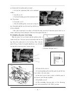
Adjusting the driving knife height
The clearance between the lower blade edge of
lower surface of the inner rotary hook should be 0.3-0.
(1) Loosen the two screws 2 and 5.
distance from the edge of the need
(1)
(2
2
o
m
ed
driving
t to adjust its position.
the driving knife 1 and the
4mm.
15
—
—
Summary of Contents for GC20688-BDC
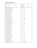
Page 24: ...A ARM BED MECHANISM 21...
Page 28: ...B THREAD TENSION REGULATOR MECHANISM 25...
Page 31: ...C NEEDLE BAR AND THREAD TAKE UP MECHANISM 28...
Page 34: ...D PRESSER FOOT MECHANISM 31...
Page 37: ...E UPPER FEED LIFTING ROCK SHAFT MECHANISM 34...
Page 40: ...F STITCH REGULATOR MECHANISM 37...
Page 43: ...G FEEDING AND FEED LIFTING HOOK SHAFT MECHANISM 40...
Page 46: ...H HOOK SADDLE MECHANISM 43...
Page 50: ...I OIL LUBRICATION MECHANISM 47...
Page 53: ...J ACCESSORIES 50...
Page 55: ...K PNEUMATIC CONTROL MECHANISM 52...
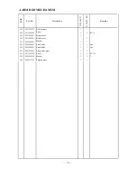
Page 57: ...L KNIFFE MECHANISM 54...


