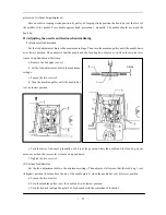
(4) Loosen the screw 3 and then move the needle bar 1 up or down to adjust so that the distance from the
tting surface of the needle plate 2 to the end of the needle bar 1 is 18.5 mm.
p between the needle and the rotary hook tip 1 is 0.1 mm.
t the level of the middle of the needle. Then
19)
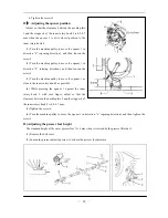
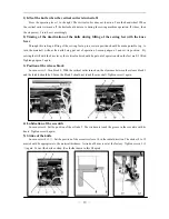
Adjusting of the needle and the hook timing
(1) Set the stitch length to “0”.
(2) Remove the needle plate.
(3) Overturn the arm.
(4) Loosen the screw 1
(5) Turn the machine pulley to raise the needle bar from its low
position to the point that the needle rises 2mm.
(6) Turn the rotary hook to align the rotary hook tip with the
center of the needle.
(7) Tighten the screw 1.
20)
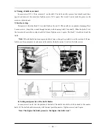
Hook protection
In looping stroke position the needle must abut on the hook
se
(5) Tighten the screw 3, install the face plate.
18)
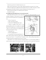
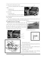
Adjusting the gap between the needle and the rotary hook tip
The ga
Set the rotary hook tip a
adjusting the gap as follow:
(1) Loosen the screws 2 and 5 (see the picture of below).
(2) Set the hook base 6 to the fit position.
(3) Rotate the adjusting plate 3, let the hook base 6 depend on the bed
plate 4.
(4) Tighten the screws 2 and 5.
—
10
—
Summary of Contents for GC20688-BDC
Page 24: ...A ARM BED MECHANISM 21...
Page 28: ...B THREAD TENSION REGULATOR MECHANISM 25...
Page 31: ...C NEEDLE BAR AND THREAD TAKE UP MECHANISM 28...
Page 34: ...D PRESSER FOOT MECHANISM 31...
Page 37: ...E UPPER FEED LIFTING ROCK SHAFT MECHANISM 34...
Page 40: ...F STITCH REGULATOR MECHANISM 37...
Page 43: ...G FEEDING AND FEED LIFTING HOOK SHAFT MECHANISM 40...
Page 46: ...H HOOK SADDLE MECHANISM 43...
Page 50: ...I OIL LUBRICATION MECHANISM 47...
Page 53: ...J ACCESSORIES 50...
Page 55: ...K PNEUMATIC CONTROL MECHANISM 52...
Page 57: ...L KNIFFE MECHANISM 54...


