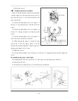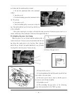
(3) Raise the presser lifters bar 1 and then loosen the screw 2.
(4) Move the outer presser bar up or down to adjust so that the height of the outer presser foot 7 is 9 mm.
he presser lifter shaft so that there is no play in the thrust direction, tighten the screw 2.
st the presser foot pressure.
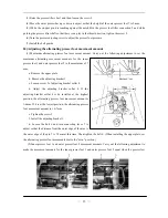
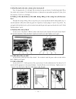
ting presser foot movement amount
lowing adjustment to set the
maximum alternating movement amounts for the inner
presser foot 1 and outer presser foot 2 to the maximum of 7
mm.
a. Remove the upper plate.
b. Remove the adjusting bracket 3.
c. Loosen screw 5 of adjusting bracket collar 4.
d. Adjust the adjusting bracket collar 4. If the
adjusting bracket collar 4 is be installed at the highest
position, the alternating presser foot movement amount is
1-6mm. If it is at the lowest position, the alternating presser
ghten the screw 5.
ver 7 to
outer presser foot 2 moveme
(5) While the stopper pin 6 is touching against the notch B in the presser foot lifter connection 5 and while
pushing t
(6) Turn the presser adjusting screw to adju
(7) Install the belt guards.
24)
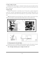
Adjusting the alterna
(1) Maximum alternating presser foot movement amount. Carry out the fol
foot movement amount is 1.6-7mm.
e. Ti
f. Install the adjusting bracket 3.
d. Loosen the bolt 6 and turn connecting le
adjust so that the distance from the outer edge of the arm to
the outer edge of the pin 7 is 78 mm at this time. Then tight
the alternating presser foot movements dial to the “min.” posi
(2) Inner presser foot 1 and
en the bolt 6. (When installing the upper plate, set
tion.)
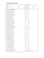
nt amounts. Carry out the following adjustment to
d outer presser foot 2 equal when the presser feet
make the movement amounts for the inner presser foot 1 an
—
13
—
Summary of Contents for GC20688-BDC
Page 24: ...A ARM BED MECHANISM 21...
Page 28: ...B THREAD TENSION REGULATOR MECHANISM 25...
Page 31: ...C NEEDLE BAR AND THREAD TAKE UP MECHANISM 28...
Page 34: ...D PRESSER FOOT MECHANISM 31...
Page 37: ...E UPPER FEED LIFTING ROCK SHAFT MECHANISM 34...
Page 40: ...F STITCH REGULATOR MECHANISM 37...
Page 43: ...G FEEDING AND FEED LIFTING HOOK SHAFT MECHANISM 40...
Page 46: ...H HOOK SADDLE MECHANISM 43...
Page 50: ...I OIL LUBRICATION MECHANISM 47...
Page 53: ...J ACCESSORIES 50...
Page 55: ...K PNEUMATIC CONTROL MECHANISM 52...
Page 57: ...L KNIFFE MECHANISM 54...


