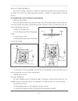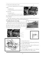
Hold a piece of paper next to the hook and check if sufficient oil is spun oil onto the paper. Remove
The hook lubrication is preset. Attach cover plate 2 again. Setting the hook lub
(3) Lubricating wicks and felt (see the picture of above)
n
7
(4)
14)
Adjusting the trailing length after thread trimming
e te
of the
ced;
creased.
15)
rse sw
n will
on wi
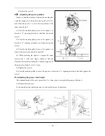
cover plate 2. Loosen screw 3 until the tube 1 no longer moves. This is the case when the tube is in the
center of the drilled hole. Turn screw 3 in until the tube movement just starts and then a 1/8 turn farther.
rication with screw 3.
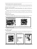
Checking the lubrication oil.
Turn on the power switch. Depress the treadle gently and check that the oil level rises in the oil sight
glass.
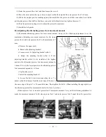
a. The wick 1 leading from the oil sump to the oscillating crank 4 must be fixed between the groove 2 i
the arm and the spring 3 of the recirculation wick.
b. When the oil satchel is changed, the flock side should be faced to connecting plate 10. The oil wick
and 8 should be set between the oil satchel 9 and plate 8.
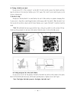
Adjust by turning the pre-tensioner 1. If th
threads trailing from the needle tips will be redu
Back tacking
When the reverse lever 1 or the quick reve
be reversed. When it is released, the feed directi
nsion of the pre-tension is increased, the lengths
if the tension is reduced, the lengths will be in
itch is pressed during sewing, the feed directio
ll return to normal.
—
8
—
Summary of Contents for GC20688-BDC
Page 24: ...A ARM BED MECHANISM 21...
Page 28: ...B THREAD TENSION REGULATOR MECHANISM 25...
Page 31: ...C NEEDLE BAR AND THREAD TAKE UP MECHANISM 28...
Page 34: ...D PRESSER FOOT MECHANISM 31...
Page 37: ...E UPPER FEED LIFTING ROCK SHAFT MECHANISM 34...
Page 40: ...F STITCH REGULATOR MECHANISM 37...
Page 43: ...G FEEDING AND FEED LIFTING HOOK SHAFT MECHANISM 40...
Page 46: ...H HOOK SADDLE MECHANISM 43...
Page 50: ...I OIL LUBRICATION MECHANISM 47...
Page 53: ...J ACCESSORIES 50...
Page 55: ...K PNEUMATIC CONTROL MECHANISM 52...
Page 57: ...L KNIFFE MECHANISM 54...


