HID FARGO DTC 5500LMX User Manual Download Page 10

Page 1-6

Specifications

PLT-02496, Version: 1.2

May 2017

1.2.4

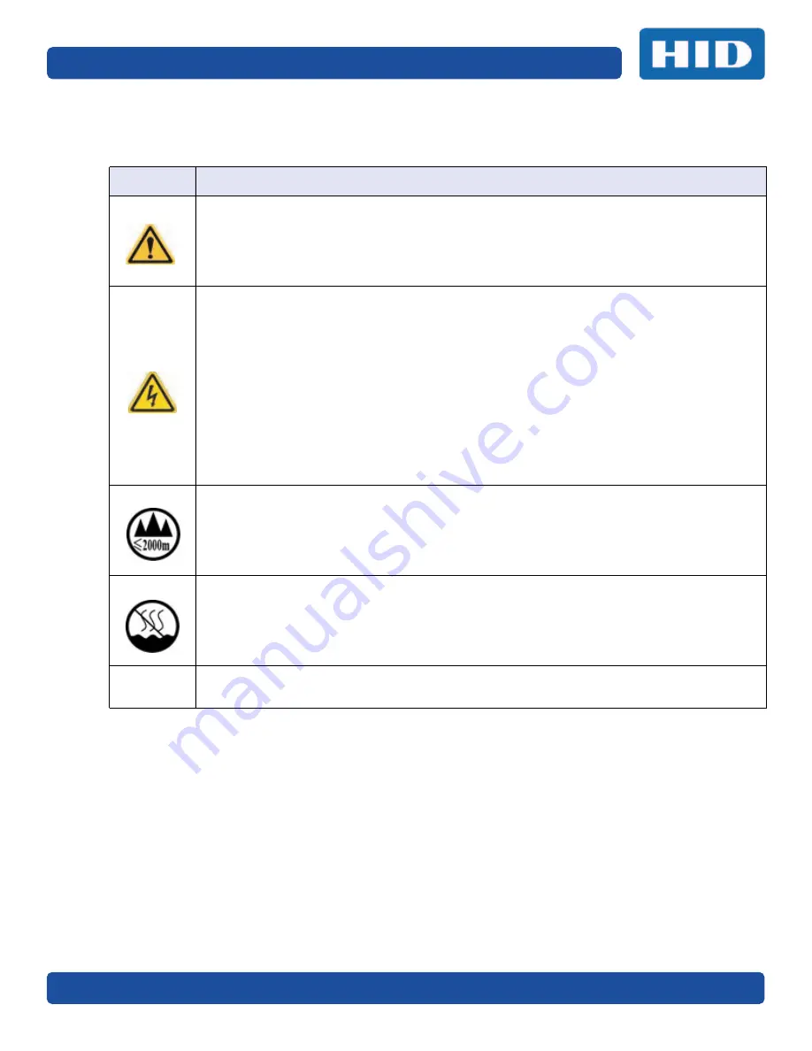
Safety Messages—China

ᆹޘ⎸᚟ ˄䈧Ԅ㓶䰵䈫˅

ㅖਧ

⎹৺ᆹޘⲴ䟽㾱䗷〻

ড䲙 

ྲ᷌н䚥ᗚ䘉Ӌᆹ㻵ᤷই䘋㹼᫽֌ˈਟ㜭Պሬ㠤䟽Քˈ⭊㠣↫ӑDŽ
ਟ㜭ᕅਁᆹޘ䰞仈Ⲵؑ᚟⭡䆖੺ㅖਧ ˄ྲᐖമᡰ⽪˅ᶕ㺘⽪DŽ
ѪҶ⺞؍Ӫ䓛ᆹޘˈ൘ᢗ㹼ࡽ䶒ᑖᴹ↔ㅖਧⲴ᫽֌ѻࡽˈ䈧ݸ䰵䈫л䶒Ⲵᆹޘ⎸᚟DŽ
ѪҶ⺞؍Ӫ䓛ᆹޘˈ䲔䶎ਖᴹ㿴ᇊˈ੖ࡉ൘ᢗ㹼㔤؞䗷〻ࡽˈ࿻㓸ᓄᯝᔰ⭥ⓀDŽ

ሿᗳ 

↔䇮༷Ѫ䶉⭥᭿ᝏ䇮༷DŽྲ᳤᷌䵢൘䶉⭥⭥⍱лˈਟ㜭Պᦏൿ䇮༷DŽ
ਟ㜭ᕅਁ䶉⭥ᆹޘ䰞仈Ⲵؑ᚟⭡䆖੺ㅖਧ ˄ྲᐖമᡰ⽪˅ᶕ㺘⽪DŽ
ѪҶ䱢→䇮༷ᡆӻ䍘ਇᦏˈ൘ᢗ㹼ࡽ䶒ᑖᴹ↔ㅖਧⲴ᫽֌ѻࡽˈ䈧ݸ䰵䈫л䶒Ⲵᆹޘ⎸᚟DŽ
ѪҶ䱢→䇮༷ᡆӻ䍘ਇᦏˈ䈧൘༴⨶⭥䐟ᶯ઼ᢃঠཤ䜘Ԧѝᡆ䱴䘁Ⲵ⭥㔶ᰦˈ䚥ᆸᡰᴹ㿴ᇊⲴ䶉
⭥᭮⭥(6'䗷〻DŽ
ѪҶ䱢→䇮༷ᡆӻ䍘ਇᦏˈ䈧࿻㓸֙ᑖ䘲ᖃⲴњӪ᧕ൠ䇮༷ ˄ֻྲˈᐢ᧕ൠ䚯ݽࠪ⧠▌൘ᦏൿ
Ⲵ儈䍘䟿㞅ᑖ˅DŽ
ѪҶ䱢→䇮༷ᡆӻ䍘ਇᦏˈ䲔䶎ਖᴹ㿴ᇊˈ੖ࡉ൘ᢗ㹼ԫօ㔤؞䗷〻ࡽˈ࿻㓸ᓄሶ㢢ᑖ઼䇱঑о
ᢃঠᵪ࠶⿫DŽ
ѪҶ䱢→䇮༷ᡆӻ䍘ਇᦏˈ൘᫽֌ᢃঠᵪࡽˈ䈧ਆл᡻ᤷ઼᡻кⲴ⨐ᇍ侠⢙ˈᒦሶ᡻кⲴ⋩␽઼
⊑␽ᖫᓅ␵⍇ᒢ߰DŽ

ӵ

㏧⏝னᾏᣆ

2000m 

௨ୗᆅ༊Ᏻ඲౑⏝

ӵ

㏧⏝ன㠀

✝ᑖ

ẻೃ᮲௳ୗᏳ඲౑⏝

⧟ຳ؍ᣔ  ѝഭ 5R+6
⧟؍֯⭘ᵏᱟสҾᵜӗ૱⭘Ҿ࣎ޜ⧟ຳDŽ

Summary of Contents for FARGO DTC 5500LMX

Page 1: ...hidglobal com FARGO DTC 5500LMX CARD PRINTER MODEL X002100 USER GUIDE PLT 02496 Version 1 2 May 2017...

Page 2: ...f their respective owners MIFARE and MIFARE DESFire are registered trademarks of NXP B V and are used under license Contacts For additional offices around the world see www hidglobal com corporate off...

Page 3: ...1 9 1 6 Printer Components Blank Cards 1 10 Chapter 2 Installation and Setup Procedures 2 1 2 1 Selecting a Good Location 2 1 2 1 1 About Moisture Condensation 2 1 2 2 Unpacking and Inspection 2 2 2 3...

Page 4: ...minator Tab 4 5 4 5 Clean Printer Tab 4 6 4 6 Advanced Settings Tab 4 7 4 6 1 Settings Information 4 8 Chapter 5 Troubleshooting 5 1 5 1 System Overview 5 1 5 1 1 Sequence of Operations 5 1 5 2 Printe...

Page 5: ...he Card Printer complies with the requirements in Part 15 of the FCC rules for a Class A digital device CE The Card Printer has been tested and complies with EN300 330 1 EN300 330 2 EN301 489 1 EN6095...

Page 6: ...rea is likely to cause harmful interference in which case correction of the interference is at the users expense IMPORTANT Changes or modifications to an intentional or unintentional radiator not expr...

Page 7: ...nsitive Damage to the device may occur if exposing it to static electricity discharges To prevent damage Reference the following safety messages before performing an operation Observe all established...

Page 8: ...ffrir des dommages s il est expos des d charges lectrostatiques Pour viter des dommages Rapportez vous aux messages suivants avant de proc der une op ration Suivez toutes les proc dures de D charges E...

Page 9: ...May 2017 PLT 02496 Version 1 2 Specifications Page 1 5 1 2 3 Safety Messages Taiwan...

Page 10: ...Page 1 6 Specifications PLT 02496 Version 1 2 May 2017 1 2 4 Safety Messages China 6 2000m 5R 6...

Page 11: ...Capacity 100 cards 030 762 mm Hopper Reject Card Capacity 100 cards 030 762 mm Interface USB 2 0 and Ethernet with internal print server Operating Conditions Operating Temperature 65 to 90 F 18 to 32...

Page 12: ...peeds do not include encoding time or the time needed for the PC to process the image Process time is dependent on the size of the file the CPU amount of RAM and the amount of available resources at t...

Page 13: ...their own unique benefits Print Ribbons are available in resin only dye sublimation only and combination dye sublimation resin versions To make it easier to remember which print ribbons are which a l...

Page 14: ...UltraCard Brand Cards The UltraCard product line available exclusively as part of HID Global FARGO brand secure card issuance solutions has a long standing reputation among dealers and end users for c...

Page 15: ...with its covers open Do not install unit near heat sources such as radiators or air ducts or in a place subject to direct sunlight excessive dust mechanical vibration or shock 2 1 1 About Moisture Con...

Page 16: ...2 0 Warranty Statement 2 3 Print Driver Installation This section describes the printer driver installation requirements and standard procedures Requirements are listed below The DTC5500LMX print dri...

Page 17: ...Installation Wizard screen prompts 1 Select Install the Printer Driver to go through the driver installation wizard 2 Select the Install the FARGO Workbench to install the Diagnostic program 3 All ver...

Page 18: ...y you must use only FARGO certified Your FARGO warranty is void where not prohibited by law if you use other than FARGO certified Printer cleaning is recommended with each ribbon change to ensure qual...

Page 19: ...the life of the printhead Card types include PVC or PVC finish Cards eject into the output hopper or reject hopper Each input hopper holds 100 cards Certain types of smart card chips are raised sligh...

Page 20: ...ted during the printer driver installation 1 Plug the power cable into the back of the printer 2 Plug the wall power cable into a standard 100 240VAC power outlet 3 Press the printer s ON OFF button t...

Page 21: ...verview of the Printing Preferences of the DTC5500LMX To locate the Printing Preferences menu select Start Devices and Printers Right click the printer icon and select Printing preferences 3 1 Card Ta...

Page 22: ...rd design program to the exact print length and width dimensions of the card Card Thickness mil Select the card thickness from the pull down list Options are 30 default and 40 mil Orientation There ar...

Page 23: ...lly detect the installed Ribbon for every print job option must be unselected for this option to be active Select from the available ribbon types on the drop down list Dual Sided Print Both Sides Prin...

Page 24: ...to accommodate the location of a chip or RFID sensor Rotate Back 180 Degrees Adjusts the orientation of the second page of the card design to accommodate the location of a chip or RFID sensor Disable...

Page 25: ...color correcting an image that has been previously printed or using third party color matching software System Color Management To perform color corrections through a complex color matching algorithm...

Page 26: ...rint Move the slider to the right to use more heat resulting in a darker or more saturated print Note This control can be helpful for fine tuning the sharpness of resin text and bar codes Resin Heat B...

Page 27: ...Move the slider to the left to decrease contrast Gamma Move the slider to the right to increase gamma in the image Move the slider to the left to decrease gamma Balance Yellow Balance Move the slider...

Page 28: ...a in relation to the card Group or Field Description Image Position Use the Image Position controls to position the image on a card Adjust the image position values by clicking on the Vertical and Hor...

Page 29: ...1 ISO Encoding Option Custom Encoding see Section 3 5 2 Custom Encoding Option Raw Binary Encoding see Section 3 5 3 Raw Binary Encoding Option JIS II Encoding see Section 3 5 4 JIS II Encoding Optio...

Page 30: ...tions are NULL SPACE ZERO Bit Density Customize the bit recording density Bits Per Inch used to encode the magnetic data on the currently selected track Options are 75 128 210 or Custom BPI LRC Genera...

Page 31: ...on With ISO Encoding a formatted set of characters are sent down This selection activates the Track tabs However all functions on the Track tabs are inactive or gray and display ISO defaults which are...

Page 32: ...Version 1 2 May 2017 3 5 2 Custom Encoding Option With Custom Encoding all options are active The default is ISO Encoding Note The defaults are the same as the ISO Encoding defaults All functions on t...

Page 33: ...ing Option With Raw Binary Encoding a raw binary string rather than a formatted set of characters is sent down The Coercivity drop down function is active and the Shift Data Left option is not active...

Page 34: ...II Encoding specific standards are used This selection disables all the Magnetic Track Options tabs the Coercivity and Shift Data Left options The default Coercivity is 600 Oe 3 5 5 ISO Track Location...

Page 35: ...these characters are not added to the track data the text intended for the magnetic track will appear as printed text on the card To avoid this track information must be entered as described below Wh...

Page 36: ...s Maximum Number of Characters Track 1 ASCII 32 95 See the table 78 Track 2 ASCII 48 63 See the table 39 Track 3 ASCII 48 63 See the table 106 ASCII Code Character ASCII Code Character ASCII Code Char...

Page 37: ...ut all functions are disabled Field Description Lamination Mode Specify the side s of the card to laminate No Lamination Front Back First Available LAM1 LAM2 Lamination Type Laminate type can be speci...

Page 38: ...just the position click on the horizontal adjustment arrows The adjustment arrows point in the direction the patch will move on the card The maximum horizontal value is 100 Pixels 10 Pixels 0 03 0 8mm...

Page 39: ...lay or Print Area Full Card Select this option to overlay and or print the entire card Defined Area s Select this option to overlay and or print only in the selected and defined area s Undefined Area...

Page 40: ...sual Security Solutions Enables a visual security option The options are only available for the Front side of a card The default value for all cards is No Visual Security This field presents options b...

Page 41: ...y Print Area from the drop down list When an option is selected a default blacked area appears on the card design area grid 3 Click and drag to enlarge or move the area to the preferred location on th...

Page 42: ...river will print areas of the image where it finds black coloring with the print ribbon resin black k panel as specified by selected options Field Description Front Back Specify the side of the card t...

Page 43: ...irectly beneath the resin black K Panel Select this option if printing resin black text or barcodes onto a colored background to provide a more gradual transition between the two Print K Only Print al...

Page 44: ...Info Tab The Printer Info tab displays information about the printer Ribbon Film Laminate LAM1 and Laminate LAM2 Group or Field Description Ribbon Indicates Ribbon Type Reorder Number and remaining le...

Page 45: ...Chapter 4 May 2017 PLT 02496 Version 1 2 ToolBox The ToolBox is located on the DTC5500LMX Card Printer Printing Preferences Card tab See Section 3 1 Card Tab for more information...

Page 46: ...checks the appropriate options The features are read only and cannot be updated If selected and no printer or modules are found an error message is displayed If this option is not selection the user w...

Page 47: ...uration tab Note The lamination module must be warm before calibrating Calibration may also be performed from the printer LCD To Calibrate the Laminator 1 Ensure that the laminate materials are instal...

Page 48: ...Calibrate the Ribbon 1 Take out the ribbon cartridge is removed 2 Ensure the Printer s cover is closed 3 Click on the Calibrate button The Printer will beep twice if the procedure was successful once...

Page 49: ...c encoding module is installed in your printer 5 Insert the Cleaning Card into the Card Hopper s in feed rollers See the diagram below 6 Click the Clean button below 7 Guide the Cleaning Card into the...

Page 50: ...tic encoding module is installed in your printer 5 Insert the Cleaning Card into the Card Hopper s in feed rollers See the diagram below 6 Click the Clean button 7 Guide the Cleaning Card into the pri...

Page 51: ...click on the numeric value in the cell click the up down arrow to modify the value or select the value and type a new value Field Description Setting This column displays the name of the Setting Defau...

Page 52: ...ncoding head Maximum adjustment range is 80 Each increment equals 01 Ribbon Print Tension Use the Ribbon Tension option to increase or decreases the amount of tension drag on the Ribbon during printin...

Page 53: ...ss directed by a technician Ribbon Green LED Level This setting is a calibration driven value and should not be adjusted Note This is factory set and should not be changed unless directed by a technic...

Page 54: ...ToolBox Page 4 10 PLT 02496 Version 1 2 May 2017 This page intentionally left blank...

Page 55: ...7 The encoded data is written to the card if applicable 8 The magnetic encoder verifies while the stepper reverses the card if applicable The print ribbon drive engages if not already at the yellow p...

Page 56: ...D will continue to stay on while the printer prints as long as there is no error This button LED will also be dimmed when the printer goes into Sleep mode When an error occurs the Pause button no long...

Page 57: ...le Error Message Cause Solution 81 Unable to Feed The printer is unable to feed a card from the input card hopper Check the following then press the Pause button to continue Verify the card thickness...

Page 58: ...r is powered up If the flipper Table is at an angle open the card output door and manually level it Then cycle the printer power to reset Reset the printer and retry If problem persists call for techn...

Page 59: ...e ON OFF button to cancel 97 Ribbon Search Error The ribbon is not able to find the next panel correctly Check for jams breaks Recalibrate the ribbon sensor If broken repair by taping the ribbon back...

Page 60: ...er Jam Home Error A card has become jammed in the printer s flipper table The flipper failed to position properly while aligning a card or flipping a card Clear any cards in the flipper table using th...

Page 61: ...t the gray latches for the hot roller mechanism to retract the hot roller mechanism to the service position Remove any obstructions Push hot roller mechanism down to return it to the ready position Cl...

Page 62: ...inter 341 Laminator Rotator Jam A Card has become jammed in the Laminator rotator station Open the Laminator lid Clear any cards in the system by pressing the card forward or backward buttons on the d...

Page 63: ...the Laminator card transport rollers Replace cleaning rollers that are dirty Close the Laminator lid Press the Resume button to continue To cancel press the Cancel Print button or the Cancel button on...

Page 64: ...he Cancel Print button or the Cancel button located on the Printer 361 LAM2 Laminate Not Ready The Laminator has reported a general fault Ensure that the laminate material is properly installed Clear...

Page 65: ...the Laminator Press the Resume button to continue If the error persists contact Technical Support 369 Laminator Calibration Error The Laminator is unable to calibrate the output hopper sensor Clear an...

Page 66: ...needs to be cleaned This icon indicates that the top input hopper is currently selected This icon indicates that the bottom input hopper is currently selected Press this button to scroll through the d...

Page 67: ...a RESIN test card Rewritable Select this choice to ERASE the Rewritable card Magnetic Select this choice to test Magnetic encoding Hi Co only Lamination Select this choice to laminate a test card Hop...

Page 68: ...Troubleshooting Page 5 14 PLT 02496 Version 1 2 May 2017 This page intentionally left blank...

Page 69: ...Card Printer Utility 2 Select the Update Manager utility 3 Select the printer s to update 4 Select the Select Firmware file option to locate or enter the latest firmware file i e DTC5500LMX_vX X X X...

Page 70: ...Firmware Upgrades Page 6 2 PLT 02496 Version 1 2 May 2017 This page intentionally left blank...

Page 71: ...support when the printer and computer are available so the Technician can help troubleshoot the printer real time 7 1 1 Reading the Serial Numbers on a FARGO Printer You can determine when your card p...

Page 72: ...Technical Support Page 7 2 PLT 02496 Version 1 2 May 2017 This page intentionally left blank...

Page 73: ...May 2017 PLT 02496 Version 1 2 Page i Revision History Date Description Document Version May 2017 General updates 1 2 May 2016 Compliance update 1 1 February 2016 Initial release 1 0...

Page 74: ...hidglobal com...

Reviews: