www.hi-velocity.com
© 1995-2017 Energy Saving Products Ltd.
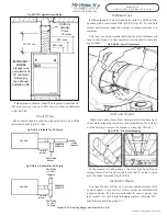
The return air duct is not supplied with the Hi-Velocity System.
It is to be supplied and installed by the contractor. The return air
and fresh air make-up ducts are to be installed according to local
building code.
The return air duct from the air handling units is to be
acoustically lined for sound absorption, for the first five feet, or
for the line of sight. This only applies on short return air duct work
of less than 10 feet (3.05m).
The return air is to be sized on a 0.15 static pressure (37 pa) as
compared to 0.10 static pressure (25 pa) for conventional forced
air systems. The maximum length for an individual return air duct
is fifty feet (15.24m).
Duct Sizing
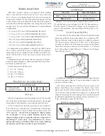
Table RA-01 has recommended return air sizes for round and
rectangular ducts. A variance of
plus 20%
is allowable for sizing
return ducts that connect to the Hi-Velocity Systems unit.
Where allowed by local codes, a single return air grill may be
used. Note: Return air grill must have equal minimum of free air
area to return air.
Return Air
Table RA-01 – Return Air Duct Sizes
Unit
Rigid Ø
Flex Ø
Min Sq.
Inches
(Sq. cm)
50/51/52
12”
(305mm)
14”
(356mm)
120
(774cm)
70/71
12”
(305mm)
14”
(356mm)
120
(774cm)
100/101
14”
(356mm)
16”
(406mm)
168
(1084cm)
Remember: When using flexible duct for return air, use
one duct size larger due to the higher friction loss.
Module RAI
Return Air Installation (1/2)
Please note: It is VERY important NOT
to undersize the return air, as this will
create noise, increase motor power
consumption and reduce airflow.
Module RAI Return Air Installation (1/2)
When designing the return air for a Hi-Velocity System, there
are a few things to consider. It is common to use centralized return
air with systems that have rooms that are within a common area.
Separate floors or rooms that have high loads and require a large
amount of supply air flow should have their own return air, or be
tied into the centralized return air to allow the air to return back
to the fan coil. Rooms or areas that cannot be tied into the return
air should have an air transfer grill to allow the air to escape the
room and flow back to a centralized return air.
The Hi-Velocity System is a pressure supply duct system that
forces the air into rooms through supply outlets. A closed room
will pressurize, and air will escape through the undercut of a door
back to a centralized return air. (i.e. a typical bedroom with two
2” outlets or 1 HE outlet will deliver 64 cfm into the space, a 1/2”
undercut door will provide 15 square inches of r/a from the space
at a transfer velocity of 4 fpm, sufficient to provide comfortable
r/a.) If more than four 2” or two HE vents are installed in a room,
or if there is a sealed door in the room, an air transfer grill or
return air should be installed to allow the air back to the fan coil.
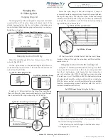
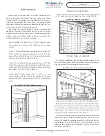
Once the placement of the return has been decided, the
return air knockout(s) can be cut. (Fig. RA-01) The pre-measured
guide cuts supplied with the fan coil should always be used; this
will guarantee maximum airflow across the coil.
Return Air Cutout
Fig. RA-01 - Return air cutout
Table RA-02 – Return Air Cutout Dimensions
Model
Dimensions
50/51 H/BU
9
1/2
” X 13
1/2
”
(241mm X 343mm)
70/71 H/BU
14” X 13
1/2
”
(356mm X 343mm)
100/101 H/BU
20” X 14”
(508mm X 356mm)
Important: When using flexible duct for
return air, use one duct size larger due to
the higher friction loss.
-19-

