www.hi-velocity.com
© 1995-2017 Energy Saving Products Ltd.
The Electrical Strip Heater (ESH) is an electric resistance heater
that slides into the fan coil on the leaving air side (supply side)
of the blower. This heater can be used for primary heating or
supplemental heat (auxiliary heating) for heat pumps. The ESH has
“0” clearance to combustibles, and requires minimum clearances
on the access side for maintenance and servicing (see Fan Coil
Placement: Module FCP). Allow 18” minimum of straight plenum
duct from the supply of the air handler before any branch outlets,
tees or elbows.
The ESH elements are rated for 240V 60 Hz. Higher voltages
are not recommended. When lower voltages are supplied, de-rate
the capacity of the ESH accordingly. 230V = 92%, 220V= 84%,
208V = 75%. Use only wires suitable for 167° F (75°C).
Wiring the Electrical Strip Heater
Electrical Strip Heater
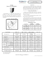
Table ESH-01
Kw
Volts/
Phase
# of
feeders
Circuit
Breakers
5
240/1
1 X 20.8
1 X 30A
10
240/1
1 X 41.6
1 X 60A’
15
240/1
1 X 20.8 1 X 41.6
1 X 30A 1 X 60A
18
240/1
1 X 31.2 1 X 41.6
1 X 40A 1 X 60A
20
240/1
2 X 41.6
2 X 60A
23
240/1
2 X 47.0
2 X 60A
Installation
The ESH is labeled with a directional airflow sticker; when
placing the ESH, the sticker shall be in the direction of the air flow.
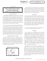
There is a minimum air flow requirement for the electric strip
heater:
The HE-B/HE-Z/HE/HV-50 fan coils and the HE-B/HE-Z/HE/HV-
70 fan coils require a minimum of six 2”x10’ AFD outlets per 5 kW.
The HE-Z/HE/HV-100 fan coils require a minimum of seven
2”x10’ AFD outlets per 5 kW.
*
One HE x 10’ AFD is equivalent to two - 2” x 10’ AFDs
Remove the shipping covers and inspect the heater carefully.
Check the ESH for any shipping damage, check the heating
elements for any loose connections and check all porcelain
insulators for any breaks. Report any damage to the manufacturer.
DO NOT INSTALL DAMAGED HEATER.
Module ESH
Electrical Strip Heater Installation (1/2)
Module ESH Electrical Strip Heater Installation (1/2)
PLEASE NOTE: THE ESH MUST BE WIRED TO A
DEDICATED BREAKER, SEPARATE FROM THE FAN COIL.
Install the ESH in the supply air side of the fan coil. Remove the
coil access door and simply slide the coil into place. The heating
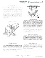
elements (Fig. 01) must always be installed horizontally. Seal the
void between the fan coil and the ESH with the foam tape supplied
with the unit or with a suitable sealant. Mount the ESH onto the
fan coil cabinet with 4 self tapping screws from inside the ESH
wiring access door. Seal any additional openings with a suitable
sealing compound.
The air handler and the ESH must have independent power
supplies.
Disconnect all power sources before opening
the control box and working within.
Wires shall be sized
according to local electrical codes and ordinances. All wires must
be brought in through knock-outs. See Table ESH-01 for feeder
quantity of feeder ampacity.
The ESH 5 and 10 kW units have one single 240V breaker; the
15 kW to 23 kW units come complete with two supply circuit
breakers. These two circuits can be joined together using a Jumper
Bar (Square D® – QOU14100JBAF, not supplied) designed to use
one pair of larger gauge wire instead of two smaller gauge wires.
Install as per manufacturers guide lines, and according to code. A
disconnect switch close to the heater will be required.
Do not install ESH as shown, with
controls on top
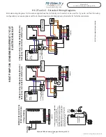
Control circuit wiring between the heater terminals #1 and #2
on the ESH use Class 2 - 18 gauge wire to the zone valve terminals
in the fan control box.
Fig. ESH-01 - Do not install elements Vertically
-38-


