www.hi-velocity.com
© 1995-2017 Energy Saving Products Ltd.
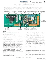
Emergency Disconnect:
C:
Common
C:
Common
Ro:
Provides 24VAC to the entire PSB board. In order for “Ro” to receive power it must be con
-
nected to terminal “Ri”. This can be done via the three pin jumper header (H1) located above
the terminal strip, a wire jumper or normally closed safety device installed between “Ro” and
“Ri”.
The jumper pin header (H1) will need to be removed to activate the emergency
disconnect option.
Ri:
Receives 24VAC direct from the transformer. Power must then be sent to the “Ro” terminal
to be distributed throughout the rest of the PSB board.
3 Pin Jumper Terminals:
H1:
Emergency Disconnect
H2 Timer:
Pump timer cycles the pump on for 5 minutes every 24 hours to prevent stagnant water.
(on/off)
The jumper pin header (H2) will need to be in the ON position for the timer
to be active.
H3 Mode:
Switches the control method used by the PSB to control motor speed.
“Auto” uses the pressure transducer in order to modulate fan speed to maintain a constant
supply pressure.
“Man” allows for direct speed control of the motor by-passing the pressure transducer.
The
jumper pin header (H3) determines the control method.
H4 Delay:
Cooling/20 second, Heating/30 second fan delay, and 30 second post purge.
The jumper
pin header (H4) will need to be in the ON position for the delay to be active.
Auxiliary Heating Relay:
N:
Neutral
L:
Line Voltage
A1:
Auxiliary Relay Normally Open
A2:
Auxiliary Relay Normally Closed
A3:
Auxiliary Relay Common
HE-Z Fan Coil - PSB Circuit Board Wiring Cont’d
-25-
Control Signal:
J8:
0-10 Volt DC Output to VFD
Module WIR
Hi-Velocity Wiring & Settings (5/10)
Module WIR Hi-Velocity Wiring and Settings (5/10)

