Installing the M.2 SATA SSD enablement option
Installing the M.2 SATA SSD enablement option
The M.2 SATA SSD enablement option includes a PCIe3 x8 add-in card (AIC) that supports two M.2 2280 SATA SSDs. This AIC is only
compatible with Windows operating systems.
CAUTION:
CAUTION:
A discharge of static electricity from a finger or other conductor might damage system boards or other static-sensitive
devices. To prevent damage, observe antistatic precautions.
Prerequisites
Prerequisites
Before you perform this procedure, make sure that you have the following items available:
T-15 Torx screwdriver
Phillips No. 1 screwdriver
Procedure
Procedure
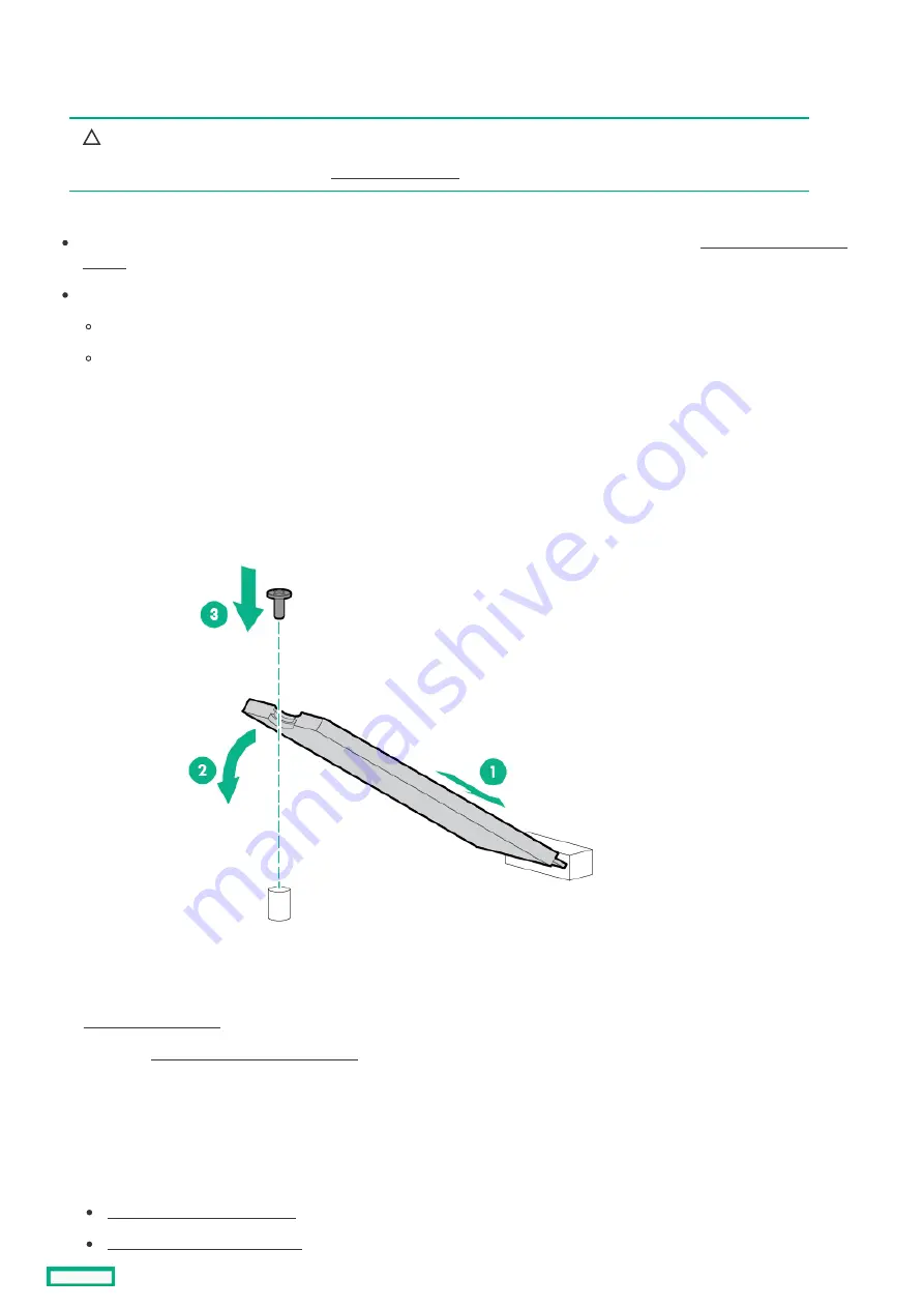
Installing the drives onto the M.2 SATA add-in card
Installing the drives onto the M.2 SATA add-in card
1. Insert the SSD into the M.2 slot at a 45° angle.
2. Carefully press the SSD down to the horizontal position.
3. Install the SSD mounting screw.
4. If you are installing a second SSD, repeat steps 1–3.
Installing the M.2 SATA SSD add-in card
Installing the M.2 SATA SSD add-in card
6. If installed, release the cable management arm .
7. Remove all power:
a. Disconnect each power cord from the power source.
b. Disconnect each power cord from the server.
8. Do one of the following:
Extend the server from the rack .
Remove the server from the rack .
Installing the M.2 SATA SSD enablement option
131
Summary of Contents for HPE ProLiant DL345 Gen10 Plus
Page 28: ...HPE Basic Drive LED definitions 28...
Page 33: ...Fan bay numbering The arrow points to the front of the server Fan bay numbering 33...
Page 46: ...Removing a riser cage 46...
Page 54: ...Operational requirements Operational requirements 54...
Page 68: ...Installing the bezel and bezel lock Installing the bezel and bezel lock 68...
Page 91: ...Connecting a DC power cable to a DC power source 91...
Page 115: ...Riser and riser cage options Riser and riser cage options 115...
Page 120: ...Expansion slots Expansion slots 120...
Page 129: ...The installation is complete Installing an accelerator or GPU 129...
Page 144: ...Installing the Trusted Platform Module board Installing the Trusted Platform Module board 144...
Page 156: ...Storage cabling Storage cabling 156...
Page 157: ...Drive power cabling Drive power cabling 157...
Page 160: ...2 SFF drive power cabling 2 SFF drive power cabling 160...
Page 161: ...Storage controller cabling Storage controller cabling 161...
Page 191: ...Energy pack cabling Energy pack cabling 191...
Page 193: ...Storage controller backup power cabling 193...
Page 194: ...M 2 SATA SSD cabling M 2 SATA SSD cabling 194...
Page 196: ...Fan cabling Fan cabling 196...
Page 197: ...OCP bandwidth upgrade cabling OCP bandwidth upgrade cabling 197...
Page 198: ...Serial port cabling Serial port cabling 198...
Page 199: ...Chassis intrusion detection switch cabling Chassis intrusion detection switch cabling 199...
Page 200: ...Front I O cabling Front I O cabling 200...
Page 201: ...Software and configuration utilities Software and configuration utilities 201...
Page 229: ...Keeping the system current Keeping the system current 229...
Page 242: ...Troubleshooting Troubleshooting 242...
Page 245: ...System battery replacement System battery replacement 245...
Page 249: ...Safety warranty and regulatory information Safety warranty and regulatory information 249...
Page 253: ...Ukraine RoHS material content declaration Ukraine RoHS material content declaration 253...
Page 255: ...Specifications Specifications 255...
Page 268: ...Support and other resources Support and other resources 268...


