


41
EN
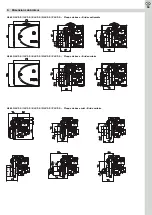
10.6 Sliding flange with additional O-ring seal
In order to satisfy the highest requirements with regard to odorous sub-
stances at the interface between the burner and the heat generator, we
recommend the employment of a sliding flange with an additional O-ring
seal. In order to achieve a maximum level of density the standard existing
boiler-side flat seal is supplemented by an additional O-ring seal. The in-
stallation of this alternative flange connection may be carried out factory
finished or by using the mixing device depending subsequently specified
conversion sets.
Order no. 10003.00172 for the mixing devices G/I/K (burner tube Ø80 mm)
or order no. 10003.00173 for the mixing devices N/P (burner tube Ø100
mm).
Conversion set consists of:
G/I/K (Ø80mm) N/P (Ø100mm)
1 Flange clamp burner side
10002.00114
10002.00116
2 Hexagon nut DIN 934 M8
10023.00002
10023.00002
3 Flange plate boiler side, S1
10002.00141
10002.00142
4 O-ring
10006.00108
10006.00059
5 Countersunk screw, DIN 965 M3x5 10023.00043
10023.00043
6 Sealing guide ring
10004.00328
10004.00362
7 Gasket for flange plate boiler side
10006.00003
10006.00126
8 Cylinder screw, DIN 7984 M8x13
10023.00063
10023.00063
9 Cylinder screw, DIN 7984 M8x30
10023.00008
10023.00008
10 Washer, DIN 125 8,4A
10023.00020
10023.00020
11 Gasket for flange clamp burner side 10006.00007
10006.00007
12 Hexagon nut DIN 934 M8
10023.00002
10023.00002
13 Cylinder screw DIN 7984 M8x30
10023.00008
10023.00008
14 Washer DIN 125 8,4A
10023.00020
10023.00020
10.7 Oil flow meter and operating hour meter
For acquisition of the used quantity of heating oil and the running period
of the burner, we offer you the installation of a combination of oil flow me-
ter and operating hour meter. The installation of the oil flow meter and
operating hour meter may be carried out factory finished, or by using the
subsequently specified conversion set (order no.: 10003.00019).
This consists of:
1 Display of oil flow meter
10030.00005
2 Cable oil firing unit - display oil meter
10013.00030
3 Cable transducer - display oil meter
10013.00031
4 Cover hood for burner with oil meter
10001.00008
5 Oil pressure line, long
10018.00006
6 Straight screw-in joint
10017.00010
7 Sealing ring
10017.00007
8 Transducer oil flow meter
10030.00006
9 Swivelling screw fitting, including sealing ring
10017.00009
10 Oil pressure line, short
10018.00007
10.8 Screw plug for the return flow connection of the
pump
To put the oil pump into one-line operation the return flow connection of
the pump has to be closed by a screw plug (order no.: 100019.00006).
Furthermore the shift screw in the junction canal between pressure and
suction side has to be removed (see Chapter 3.5).
10.9 Service case
In order to have all necessary spare parts ready for an on-site service on
the burner we offer you an individual service case for the respective burner
and your requirements.
Please do not hesitate to contact us for further information.
11. Customer service
For further information on the burner and for ordering spare parts please
do not hesitate to contact our Customer Service Department at:
Herrmann GmbH u. Co. KG
Phone: 00 49 7151 98928-0, Fax: 00 49 7151 98928-49
Email: [email protected]
1
2
3
4
5
6
7
8
9
10
3
4
5
6
7
8
1
9
10
11
12
13
14
2
Burner pipe
Flange clamp
burner side
Sealing guide ring
Flange plate,
boiler side S1
O-ring
(additional
sealing)
Sealing for flange plate
boiler side
(standard sealing)