


Installation and operating
instructions
Notice de montage et
de service
Montage- en bedienings-
handleiding
F
NL
GB
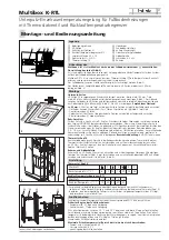
Multibox K-RTL est à monter dans le circuit de retour à la fin
du circuit de chauffage par le sol
. Tenir compte du sens du
courant (Fig. 2)
S’assurer que la température de la canalisation montante de l’instal-
lation convient à la conception du système de chauffage par le sol.
Placer Multibox K-RTL de manière telle que la tête de thermostat
puisse saisir la température de l'air ambiant et être contournée sans
problème par celui-ci.
Veiller à ce que la température de la canalisation montante de l’installa-
tion soit appropriée à la structure du système du chauffage par le sol.
Le tube du chauffage par le sol doit être posé dans la chape en
forme de spirale (Fig. 2).
L’écart du sol fini doit être de 200 mm au moins à partir du bord
inférieur du caisson à encastrer (Fig. 3).
Instructions de montage
Rail de fixation
Radiateur
Caisson à encastrer
Circuit de chauffage par le sol
Soupape de purge / de rinçage
Couche extérieure du mur
Limiteur de température de retour RTL
Bord supérieur sol fini
Vis d’arrêt 4.2 x 19
Plaque de recouvrement
Raccord de tube G 3/4 AG
Vis 4.2 x 50
Tête de thermostat K
Cadre
Légende
Caisson à encastrer
Placer le caisson à encastrer
bien d’aplomb dans la fente ménagée à cet effet
dans le mur (largeur au moins 144mm, profondeur 60 mm) et le monter
ensuite à l'aide de rails de fixation (Fig. 3). L’écart entre le bord avant du
caisson à encastrer et le mur fini peut se situer entre 0 et 30 mm du fait du
couvercle variable constitué de la plaque de recouvrement
et du cadre
[Fig. 4).
Ecart recommandé : env. 20 mm.
Aligner le caisson à encastrer
comme suit pour qu’il ait la position désirée au-dessous du mur fini.
– Déterminer l’épaisseur de la couche extérieure du mur (enduit,
carrelage, placoplâtre etc.)
(Fig. 3).
– Desserrer les vis d’arrêt
.
– Aligner le bord avant du caisson à encastrer pour qu’il ait la
position désirée au-dessous du mur fini.
– Resserrer les vis d’arrêt
.
Raccord de tube
Pour le raccordement de tubes en plastique, en cuivre, en acier de préci-
sion et de tubes d’assemblage, utiliser uniquement les vissages par serrage
appropriés et originaux de HEIMEIER. La bague de serrage, l’écrou de la
bague de serrage et l’embout à olive portent l’indication de la taille et
l’inscription THE. Dans le cas de bagues à compression à obturation
métallique pour tubes en cuivre ou acier de précision, d'une épaisseur de
paroi entre 0,8 et 1,0 mm, utiliser des douilles de renforcement pour une
meilleure stabilisation du tube. Scier ensuite les tubes à la longueur
nécessaire perpendiculairement à l’axe du tube. Les extrémités du tube
doivent être parfaitement rondes et impeccables et ne présenter ni
ébarbures ni dommages. Après le raccordement du tube, placer le
cou-
vercle de protection pour les travaux
ci-joint dans le caisson à encas-
trer.
Tête de thermostat K
Lorsque les travaux de tubage sont terminés, enlever le couvercle de
protection pour les travaux. Placer la tête de thermostat sur la base de
la soupape de thermostat, la visser et le serrer fermement à l’aide
d’une pince à mors en caoutchouc (env. 20 Nm). Veiller à ce que la
flèche de réglage soit orientée vers le haut. Positionner ensuite la tête
de thermostat sur le chiffre de référence 3.
Cadre et plaque de recouvrement
Monter le couvercle
sur le caisson à encastrer
, le centrer correc-
tement à l'aide des vis
ci-jointes. Le cas échéant, enlever les clips
à économie d’énergie et placer ensuite la plaque de recouvrement
sur le cadre et faire pression jusqu’à ce qu’elle s'enclenche (Fig. 4).
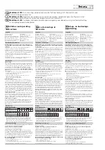
Montage
Réglage
1
2
3
4
5
10
20 30 40
50
1
2 3
4
5
2
14
16
20
24
28
6
1
Tête de thermostat K
Limiteur de température du circuit de retour RTL
Chiffre de référence
Température de la pièce
Chiffre de référence
Température du circuit de retour
Sous réserve de modifications techniques.
De Multibox K-RTL dient in de terugloop aan het einde van de vloerver-
warmingskring
te worden aangesloten. Let op de stroomrichting (afb. 2).
Houd er rekening mee dat de door de installatie geschakelde voorlooptemperatuur ook
geschikt moet zijn voor de systeemopbouw van de vloerverwarming. U dient de
Multibox K-RTL zodanig te plaatsen dat de thermostaat-kop
de temperatuur van
de kamerlucht kan detecteren en dat de kamerlucht ongehinderd om de thermo-
staat kan circuleren.
Houd er rekening mee dat u de door de installatie geschakelde voorlooptemperatu-
ur ook geschikt moet zijn voor de systeemopbouw van de vloerverwarming.
De vloerverwarmingsbuis dient in de vorm van een spiraal in de estrik te worden
gelegd (afb. 2).
De afstand tot de montagevloer dient vanaf de onderzijde van de verzonken kast
minimaal 200 mm te bedragen (afb. 3).
Montageaanwijzingen
Bevestigingsrail
Radiator
Verzonken kast
Vloerverwarmingskring
Ontluchtings-/spoelklep
Buitenste muurlaag
Terugloop-temperatuurbegrenzer RTL
Bovenzijde montagevloer
Vastzetschroef 4.2 x 19
Afdekplaat
Buisaansluiting G 3/4 AG
Schroeven 4.2 x 50
Thermostaatkop K
Frame
Legenda
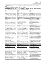
Montage
Instelling
1
2
3
4
5
10
20 30 40
50
1
2 3
4
5
2
14
16
20
24
28
6
1
Thermostaatkop K
Terugloop-temperatuurbegrenzer RTL
Kengetal
Kamertemperatuur [° C]
Kengetal
Teruglooptemperatuur [° C]
Technische wijzigingen voorbehouden.
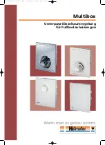
Multibox K-RTL
Flush mounting individual room control for floor heating with thermostatic valve
and return temperature limiter
Multibox K-RTL
Régulateur de température à encastrer pour pièces individuelles pour chauffages par le sol
avec soupape de thermostat et limiteur de température du circuit de retour
Multibox K-RTL
Verzonken individuele kamertemperatuurregeling voor vloerverwarming met thermostaatklep
en terugloop-temperatuurbegrenzer
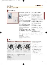
Multibox K-RTL is to be connected in the return flow at
the end of the floor heating circuit
. Note flow direction
(illustr. 2).
It should be seen to that the system supply temperature is
suitable for setting up the floor heating system.
Multibox K-RTL is to be placed so that the thermostatic head K
reads the room air temperature and that the air can flow past it.
It has to be taken into account that the supply temperature used
is suitable for the construction of the floor heating.
The floor heating pipe should be laid in a spiral form in the
flooring (illustr.2).
The distance from the lower edge of the flush casing to the
finished floor should be at least 200 mm (illustr.3).
Installation information
Mounting rail
Radiator
Flush casing
Floor heating circuit
Air venting / flushing valve
Outer wall layer
Return temperature limiter RTL
Finished floor upper surface
Locking screw 4.2 x 19
Cover plate
Pipe connection G 3/4 outside thread
Screws 4.2 x 50
Thermostatic head K
Frame
Legend
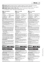
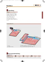
Installation
Adjustment
1
2
3
4
5
10
20 30 40
50
1
2 3
4
5
2
14
16
20
24
28
6
1
Thermostatic head K
Return temperature limiter RTL
Index figure
Room temperature [° C]
Number
Return temperature [° C]
- Recommendation: set the hidden restriction or locking of the
required return temperature. See the leaflet Installation and
Operating Instructions (with thermostatic head K operation).
- Make sure that the setting is not lower than the ambient tempe-
rature of the RTL since then it will no longer open.
Carry out functional heating at the heating mark conforming
to standards in keeping with EN 1264-4.
Earliest start for functional heating:
– Cement floor: 21 days after laying
– Anhydrite floor: 7 days after laying
Begin at supply temperature of 20°C - 25°C and maintain
for 3 days. Then adjust maximum design temperature and
maintain for 4 days. The supply temperature can be regulated
by controlling the boiler. Turn the protective cap anticlockwise
to open valve and turn RTL head to Position 5.
Refer to the information of the cement floor manufacturer!
Do not exceed maximum cement floor temperature
at the heating pipes:
– Cement and anhydrite floor: 55 °C
– Poured asphalt floor: 45°C
– in line with particulars of the cement floor manufacturer!
Functional heating
Exécuter le chauffage fonctionnel dans le respect des normes sur les chapes
chauffantes EN 1264-4.
Début du chauffage fonctionnel au plus tôt :
– Chape de ciment : 21 jours après la pose
– Chape anhydrite 7 jours après la pose
Commencer avec une température de canalisation montante entre 20 et 25 °C
et la maintenir pendant 3 jours. Régler ensuite la température de pose maxima-
le et la maintenir pendant 4 jours. La température de la canalisation montante
sera régulée à l’aide de la commande du générateur thermique. Ouvrir le
robinet en tournant le capuchon de protection vers la gauche et en tournant la
tête RTL en position 5. Observer les indications du fabricant de la chape.
Ne pas dépasser la température de chape maximale dans
la zone des tuyaux de chauffage :
– Chape ciment et anhydride : 55 °C
– Chape d’asphalte coulé : 45 °C
– Selon les indications du fabricant de la chape.
Chauffage fonctionnel
Start het verwarmingsbedrijf bij normgerechte verwarmingsestrik conform
EN 1264-4.
Vroegst mogelijk begin van het verwarmingsbedrijf
– Cementestrik: 21 na het leggen
– Anhydrietestrik: 7 na het leggen
Begin met een voorlooptemperatuur van 20 °C t/m 25 °C en handhaaf deze
3 dagen. Stel vervolgens de maximale uitvoeringstemperatuur in en hand-
haaf deze 4 dagen. De voorlooptemperatuur moet daarbij worden geregeld
via de besturing van de warmtegenerator. Open de klep door het naar links
draaien van de montagekap en draai de RTL-kop naar stand 5.
Let op de aanwijzingen van de estrikfabrikant!
Overschrijd nooit de maximale estriktemperatuur in het
bereik van de verwarmingsbuizen:
– cement- en anhydrietestrik: 55 °C
– gietasfaltestrik: 45 °C
– volgens de gegevens van de estrikfabrikant!
Begin van het verwarmingsbedrijf
Technical changes must be taken into account.
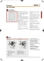
Flush casing
Place the flush casing
vertically in the wall slot provided
(width at least 144 mm, depth at least 60 mm) and fix with
the mounting rails (illustr. 3). By means of the variable cover,
consisting of cover plate
and frame
(illustr. 4), the
distance between the front edge of the flush casing and
finished wall can be 0 to 30 mm.
Recommended distance
20 mm.
Align flush casing to the position required below the
finished wall:
- Determine thickness of the outer wall layer (plaster, tiles,
gypsum plaster board etc.)
(illustr. 3).
- Loosen locking screw
.
- Align front edge of the flush casing to the position
required below the finished wall.
- Tighten up locking screw
again.
Pipe connection
Use only original HEIMEIER compression fittings for the
connection of plastic, copper, precision steel or multi-layer
pipe. Compression ring, compression ring nut and hose
nozzle are marked with dimensional information and with
THE. When metallically sealing compression fittings are used
with copper or precision steel pipe, with a pipe wall thickness
of 0.8 – 1.0 mm, use supporting sleeves for the additional
stabilisation of the pipe. Cut the pipes to be connected into
sections at right angle to the pipe axis. The pipe ends must
be perfectly round, free of burrs and undamaged. After con-
necting the pipe fit the
protection cover
in the flush casing.
Thermostatic head K
Take off the protection cover after completion of the structural
work. Place the thermostatic head on the thermostatic valve
body, screw up and tighten with rubber jawed wrench
(approx. 20 Nm). Make sure that the setting arrow point
upwards. Afterwards set the thermostatic head to number 3.
Frame and cover plate
Put on frame
and flush casing
, align them and fasten
with the screws
enclosed. If necessary withdraw the
economy clips on the thermostatic head K and afterwards
put on the cover plate
and press it until it clicks into
place (illustr. 4).
Verzonken kast
Plaats de verzonken kast
loodrecht in de desbetreffende wand-
gleuf (breedte minimaal 144 mm, diepte minimaal 60 mm) en ver-
volgens met behulp van bevestigingsrails monteren (afb. 3). De
afstand tussen de voorzijde van de verzonken kast en de montage-
wand kan met de
variabele afdekking, bestaande uit de afdekplaat
en het frame
(afb. 4), 0 tot 30 mm bedragen.
Aanbevolen afstand: ca. 20
mm.
Lijn de verzonken kast als volgt uit op de gewenste positie
beneden de montagewand:
- bepaal de dikte van de buitenste muurlaag (pleister, tegels, gips-
plaat enz.)
(afb. 3).
- draai de vastzetschroeven
los.
- lijn de voorzijde van de verzonken kast als volgt uit op de
gewenste positie beneden de montagewand:
- draai de vastzetschroeven
weer aan.
Buisaansluiting
Gebruik voor de aansluiting van een kunststof-, koper-, precisiestaal- of
compositiebuis alléén de desbetreffende originele HEIMEIER-klem-
schroefverbindingen. Klemring, klemringmoer en slangtule zijn geken-
merkt met de maatgegevens en met THE. Maak bij metallisch afdichten-
de klemschroefverbindingen voor koper- of precisiestaalbuizen met een
buiswanddikte van 0,8 mm - 1,0 mm gebruik van steunmanchetten
voor een betere stabilisatie van de buis. Zaag aan te sluiten buizen pas
- en wel haaks op de buisas. Buiseinden moeten optimaal rond, braam-
vrij en onbeschadigd zijn.
Plaats na de buisaansluiting de bijgevoegde
montagebeveiliging
in de
verzonken kast.
Thermostaatkop K
Verwijder de montagebeveiliging na de beëindiging van de buiswerk-
zaamheden. Plaats de thermostaatkop op de thermostatische afsluiter,
schroef deze aan en trek deze vast met een tang met rubberbekken
(ca. 20 Nm). Let op dat de instelpijl naar boven wijst. Zet vervolgens
de thermostaatkop op het kengetal 3.
Frame en afdekplaat
Plaats het frame
tegen de verzonken kast
, lijn het uit en bevestig
het met de bijgevoegde schroeven
. Trek eventueel de spaarclips aan
de thermostaatkop K terug. Plaats vervolgens de afdekplaat
tegen
het frame en druk de plaat aan totdat deze inklikt (afb. 4).
- Advies: voer verborgen begrenzing of blokkering van de gewenste teru-
glooptemperatuur uit. Zie ook de brochure “Montage- en bedienings-
handleiding” (bij bediening van de thermostaatkop K).
- Let op dat de ingestelde waarde niet lager ligt dan de omgevingstempe-
ratuur van de RTL omdat deze dan niet meer zou openen.
– Recommandation : Procéder à une limitation cachée ou à un blocage de
la température désirée du circuit de retour. Voir prospectus notice de
montage et de service (en cas d’utilisation de la tête de thermostat K).
– Veiller à ce que la valeur prescrite réglée ne soit pas inférieure à la
température ambiante, sinon celle-ci ne s’ouvre plus.


