background image

25

Heat & Glo  •  6000TRSI-AUC  •  2078-900 Rev. Q  •  6/10

H.  Installer Testing

The space heater must be tested and be operating accord-
ing to manufacturers specifi cations prior to the installer 
leaving the site. Note: the tips of the fl ames should never hit 
the top of the fi rebox after the unit has warmed up. Please 
contact your dealer or a qualifi ed service person to replace 
injector or adjust valve.

Upon completing the gas line connection, a small amount 
of air will be in the lines. When fi rst lighting the pilot light, 
it will take a few minutes for the lines to purge themselves 
of this air.  Once the purging is complete, the pilot and 
burner will light and operate as indicated in the Lighting 
Instructions.

Subsequent lightings of the appliance will not require such 
purging.

Follow the Safety Information and Lighting Instructions 
pages of this manual to light the appliance.

To obtain proper operation, it is imperative that the pilot 
and main burner fl ame characteristics are steady, not lift-
ing or fl oating.  Typically, the top 3/8 inch (9.5 mm) of the 
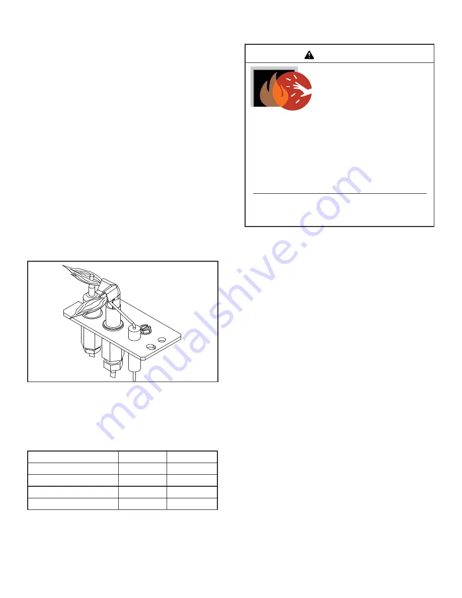
thermocouple should be engulfed in the pilot fl ame. (See 
Figure 1.35).  See Table 1 for pressure requirements.

Figure 1.35

Pilot Assembly

This appliance is a balanced fl ue heater and is designed 
to operate with all combustion air being siphoned from the 
outside of the building and all exhaust gases expelled to 
the outside of the building.

WARNING: THIS UNIT IS NOT FOR USE WITH SOLID 
FUEL.

The control system for this model employs an electronic 
pilot ignition. It consists of a 6V gas control valve/variable 
regulator, an electronic module, a thermocouple and a 
remote control. The controls are located in the lower com-
partment behind the lower door, and access is gained by 
lifting the door up. See Figure 1.  

WARNING: DO NOT CONNECT 220-240 VAC TO THE 
GAS CONTROL VALVE OR CONTROL WIRING SYSTEM 
OF THIS UNIT.

When lit for the fi rst time, the appliance will emit a slight 
odor for an hour or two. This is due to paint and lubricants 
used in the manufacturing process. Additionally, for the 
fi rst few minutes after each lighting, vapor may condense 
and fog the glass and the fl ames may be blue.  After a 
few minutes this moisture will disappear and within 15-30 
minutes the fl ames should become yellow.

The heater may produce a noise, caused from metal ex-
pansion and contraction as it heats up and cools down. 
This noise is similar to one that a furnace or heat duct may 
produce and does not affect the operation or longevity of 
the heater.

Table 1.

Follow TROUBLESHOOTING section for adjusting the 
appliance to operate properly.

Natural Gas

Propane Gas

Inlet Pressure

1.13 kPa

2.75 kPa

Outlet Pressure

.80 kPa

2.36 kPa

Max. Gas Consumption 

36.0 mJ/h

34.0 mJ/h

Burner Injector

2.87 mm

1.70 mm

2.0  OPERATING INSTRUCTIONS

WARNING

This appliance has been supplied with an integral barrier 
to prevent direct contact with the fi xed glass panel. DO 
NOT operate the appliance with the barrier removed. 

HOT SURFACES

Glass and other surfaces are hot during 
operation AND cool down.

Hot glass will cause burns.

• 

DO NOT

 touch glass until it is cooled

•  NEVER allow children to touch glass
•  Keep children away

•  CAREFULLY SUPERVISE children in same room as 

fi replace.

•  Alert children and adults to hazards of high temperatures.

High temperatures may ignite clothing or other 
fl ammable materials.

•  Keep clothing, furniture, draperies and other fl ammable 

materials away.

Summary of Contents for 6000TRSI-AUC

Page 1: ...lts to hazards of high temperatures High temperatures may ignite clothing or other flammable materials Keep clothing furniture draperies and other flammable materials away This appliance has been supp...

Page 2: ...l Report to your dealer any parts dam aged in shipment specifically check glass condition The gas logs and flue system components are in separate packages PLEASE READ THIS MANUAL BEFORE INSTALLING AND...

Page 3: ...F Mantel Clearances 22 G Log Placement 23 H Installer Testing 25 2 0 OPERATING INSTRUCTIONS 25 A Safety and Lighting Information 27 B Power Outage 28 C Fan Operation 28 3 0 SERVICING AND MAINTENANCE...

Page 4: ...peting or tile or on any combustible material other than wood flooring the heater should be installed on a metal or wood panel that extends the full width and depth of the heater A B C D E FRONT VIEW...

Page 5: ...g 36 inches 914 mm 0 1 2 inch 13 mm 1 2 inch 13 mm 3 1 2 inches 89 mm 31 inches 787 mm Minimum Clearances from the Flue Pipe to Combustible Materials For Horizontal Sections For Vertical Sections At W...

Page 6: ...oned to accommodate wall coverings and heater facing material The diagram below shows framing reference dimensions NOTE These dimensions show the center of the horizontal flue pipe The center of the f...

Page 7: ...e box P 500 f From a drain or soil pipe 150 g Horizontally from any building structure unless appliance approved for closer installation or obstruction facing a terminal 500 h From any other flue term...

Page 8: ...n this gas heater may include one two or three 90 elbow assemblies The relationships of vertical rise to horizontal run in flue configurations using 90 elbows MUST BE strictly adhered to The rise to r...

Page 9: ...RATE FLUE SYSTEM COMMON FLUE SYSTEMS ARE PROHIBITED CAUTION UNDER NO CONDITION SHOULD COM BUSTIBLE MATERIAL BE CLOSER THAN 3 INCHES 2 1 2 INCHES AT WALL FIRESTOPS FROM THE TOP OF THE 8 INCH PIPE OR 1...

Page 10: ...imen sions and dimension H H1 is listed as corresponding TOTAL MAXIMUM horizontal dimensions THREE 3 90 DEGREE ELBOWS Figures 1 13 through 1 15 show examples of possible installations using three 3 90...

Page 11: ...4 MAX 1 22 M 12 MAX 3 66 M 4 MIN 1 22 M 6 MAX 1 83 M 16 MAX 4 88 M 20 MAX 6 10 M 6 MAX 1 83 M 16 MAX 4 88 M H1 V H V FT H FT 1 MIN 0 30 M 4 MAX 1 22 M 2 MIN 0 61 M 8 MAX 2 44 M 3 MIN 0 91 M 12 MAX 3 6...

Page 12: ...900 Rev Q 6 10 V FT H H1 FT 1 MIN 0 30 M 4 MAX 1 22 M 2 MIN 0 61 M 8 MAX 2 44 M 3 MIN 0 91 M 12 MAX 3 66 M 4 MIN 1 22 M 16 MAX 4 88 M V H H1 36 MAX 10 97 M V V1 H 36 MAX 10 97 M H1 H V V V1 H Figure 1...

Page 13: ...6 MAX 1 83 M 9 MAX 2 74 M 4 MIN 1 22 M 8 MAX 2 44 M 12 MAX 3 66 M 8 MAX 2 44 M 12 MAX 3 66 M NOTE V V MAX 36 10 97 M FLUEING WITH THREE 3 90 ELBOWS Figure 1 13 Flueing with three 90 elbows V H H H1 H...

Page 14: ...0 30 M 3 MAX 0 91 M 2 MIN 0 61 M 6 MAX 1 83 M 3 MIN 0 91 M 9 MAX 2 74 M 4 MIN 1 22 M 12 MAX 3 66 M NOTE V V1 H H1 32 MAX 9 75 M V FT H H1 FT 1 MIN 0 30 M 3 MAX 0 91 M 2 MIN 0 61 M 6 MAX 1 83 M 3 MIN 0...

Page 15: ...ons accord ingly Flueing Out the Rear Flue Remove the installed rear seal cap from the rear start ing collars by cutting the strap at each end See Figure 1 16 Follow the flue configuration tables acco...

Page 16: ...to make sure they have snapped together see Figure 1 20 and the seams are not aligned see Figure 1 21 Tug slightly on section A to confirm it has completely locked into place Figure 1 19 Figure 1 20 F...

Page 17: ...ses To install firestops heat shield for horizontal runs that pass through either interior or exterior walls Cut a 10 inch by 12 inch 254 mm X 305 mm hole through the wall Position the firestops on bo...

Page 18: ...eat shield is attached to the wall shield The other is attached to the termination cap in the same manner The heat shield sections will overlap to match the wall thickness depth If the wall thickness...

Page 19: ...pes Cut and frame the roof hole Use framing lumber the same size as the roof rafters and install the frame securely Flashing anchored to the frame must withstand heavy winds Continue to install concen...

Page 20: ...N MODULE 6V ON OFF WALL SWITCH VALVE FLAME SPARKER SENSOR ANT REMOTE CONTROL HOT NEUTRAL GROUND BATTERY PORT VALVE PILOT IGNITION MODULE 6VDC ON OFF SWITCH THERMOCOUPLE BLOCK CONNECTED TO BACK OF VALV...

Page 21: ...switch for the blower fan These components are located behind the lower door The factory installed power cord is attached on the lower front right exterior side of the heater Figure 1 31 shows the bl...

Page 22: ...ESE JOINTS ARE NOT REQUIRED TO BE SEALED ONLY NON COMBUSTIBLE MATERIAL USING 150 C MINIMUM ADHESIVE IF NEEDED CAN BE APPLIEDAS FACING TO THE HEATER SURROUND SEE Figure 1 34 FINISH WALL MATERIAL MAY BE...

Page 23: ...Carefully remove the logs from the packaging LOG 2 SRV2049 701 Locate log 2 on grate with notches Slide back against tabs Log Assembly LOG 6TRSI AUC 2 2 TABS 1 LOG 1 SRV2049 700 Locate log 1 by placin...

Page 24: ...grate bar and rest its top into the groove on log 1 LOG 5 SRV385 723 Position log 5 between the 3rd and 4th grate bar resting on the grooves in log 1 and log 2 5 5 4 4 LOG 3 SRV385 721 Rest log 3 in...

Page 25: ...rmocouple and a remote control The controls are located in the lower com partment behind the lower door and access is gained by lifting the door up See Figure 1 WARNING DO NOT CONNECT 220 240 VAC TO T...

Page 26: ...CAN BE PLACED INTO SAFE OPERA TION DO NOT USE THISAPPLIANCE IFANY PART HAS BEEN UNDER WATER IMMEDIATELY CALL A QUALIFIED SERVICE TECHNICIAN TO INSPECT THE UNIT AND TO REPLACE ANY PART OF THE CONTROL S...

Page 27: ...n electronic pilot ignition device which automatically lights the burner Do not try to light the burner by hand B BEFORE LIGHTING smell all around the heater area for gas Be sure to smell next to the...

Page 28: ...h warms up and stop the fan when it cools down You can manually stop the fan by turning the speed control switch to OFF See Figure 1 30 for fan wiring diagram SWITCH IS SHOWN IN ON POSITION Figure 2 2...

Page 29: ...DOOR WHEN IT IS HOT 6 The glass door should be cleaned using a house hold glass cleaner DO NOT handle or attempt to clean the glass when it is HOT 7 Visually inspect the flexible power supply cord if...

Page 30: ...connectors apart and slide the fan out the front of the lower controls compartment Disconnect the wires from the fan speed control switch pull off the knob and remove the nut holding the speed contro...

Page 31: ...Inspect for paint condition warpage corrosion or perforation Sand and repaint as necessary 2 Replace appliance if firebox has been perforated Burner Ignition and Operation 1 Verify burner is properly...

Page 32: ...loca tion along cable d Valve Replace valve Do not over tighten e Over tightened thermocouple interrupter Replace valve and thermocouple interrupter f Receiver Replace receiver and reprogram code 5 P...

Page 33: ...ing at the base of the burner It is imperative that NO material be placed in this opening 11 Flame burns blue and lifts off burner a Insufficient oxygen being supplied 1 Check to make sure flue cap is...

Page 34: ...Rev Q 6 10 Log set assembly Service Parts Diagram 4 0 Replacement Parts Beginning Manufacturing Date 6 06 Ending Manufacturing Date ______ 6000TRSI AUC Part number list on following page 7 8 9 10 11...

Page 35: ...GLA 6TRXI 10 Surround Pre Aug 2009 SRV2101 260 Post Aug 2009 2166 019 11 Hood SRV60 143 BK 12 Insulation Board 385 401 13 Top Louver 392 182A 14 Lower Door 2078 041 15 Dress Guard 2078 040 16 Blower A...

Page 36: ...M DESCRIPTION COMMENTS PART NUMBER 1 Pilot Assembly N 2098 050 Pilot Assembly P 2098 051 2 Pilot Bracket 2078 108 3 Gasket Valve Plate 2166 162 4 Valve Bracket 2118 104 5 Rheostat 491 510A 6 Rheostat...

Page 37: ...37 Heat Glo 6000TRSI AUC 2078 900 Rev Q 6 10 Limited Lifetime Warranty...

Page 38: ...38 Heat Glo 6000TRSI AUC 2078 900 Rev Q 6 10...

Page 39: ...pport DVP WS Wall Shield Firestop DVP FS Ceiling Firestop DVP45 45 Elbow DVP Pipe see chart Effective Height Length 276 mm 13 mm TYP Assembled Height 610 mm Diameter 254 mm DVP AS2 203 m m 45 Pipe Eff...

Page 40: ...fective Length Heat Shield Note Heat shields MUST overlap by a minimum of 38 mm The heat shield is designed to be used on a wall 102 mm to 184 mm thick If wall thickness is less than 102 mm the existi...

Page 41: ...DVP HSM B Extended Heat Shield 305 mm 184 mm 133 mm 318 mm DVP TVHW VerticalTermination Cap Highwind 330 mm 381 mm 206 mm 276 mm 267 mm 3 87 Effective Length 146 to 213 mm 140 mm 213 mm DVP HRC SS DV...

Page 42: ...6 10 For Service or Replacement Parts Contact Melbourne Jetmaster 444 Swan Street Richmond 3121 03 9429 5573 Perth Fireplace Corner 277 Lord Street East Perth 6000 08 9228 2600 Sydney Jetmaster 10 Ma...

Reviews: