HBM QuantumX MX1609 Operating Manual Download Page 168

167

Accessories

HBM

QuantumX

MX840/MX840A accessories

Article

Description

Order No.

Cold junction for thermocouple on MX840,

MX840A, MX440

Electronics for temperature compensation for measurements

with thermocouples on MX840, MX840A, MX460, comprising:

 PT1000 cold junction

 Including 1-wire TEDS chip for transducer identification

Note: Mounting in D

Sub

HD 15-pin transducer plug.

1-THERMO-MXBOARD

Adapter D

Sub

HD15 to D

Sub9 (CAN) on

MX840, MX840A

Adapter for connecting CAN devices to MX840, MX840A,

MX460. D

Sub

HD 15-pin (plug) to D

Sub 9-pin (socket);

(length: approx. 30 cm).

1-KAB418

MX410 accessories

Article

Description

Order No.

BNC adapter for IEPE sensors with BNC

Adapter for connecting IEPE sensors with BNC connection

cable to MX410 (BNC socket to 15-pin D

Sub

HD; length:

approx. 7 cm).

1-IEPE-MX410

MX1609, 1609P and 1609T accessories

Article

Description

Order No.

Bag with 10 mini thermocouple plugs, incl. RFID

for thermocouple type K

Packet, comprising 10 x mini thermocouple plugs with

integrated RFID chip for measuring point detection for the

MX1609 thermocouple measuring amplifier of the QuantumX

product family; Type K: NiCr

NiAl, RFID integrated, green,

male.

1-THERMO-MINI

Bag with 10 mini thermocouple plugs, incl. RFID

for thermocouple type T

Packet, comprising 10 x mini thermocouple plugs with

integrated RFID chip for measuring point detection for the

MX1609 thermocouple measuring amplifier of the QuantumX

product family; Type T: Co

CoNi, RFID integrated, brown,

male.

1-THERMO-MINI

T

MX879, MX1601  and 1615 accessories

Article

Description

Order No.

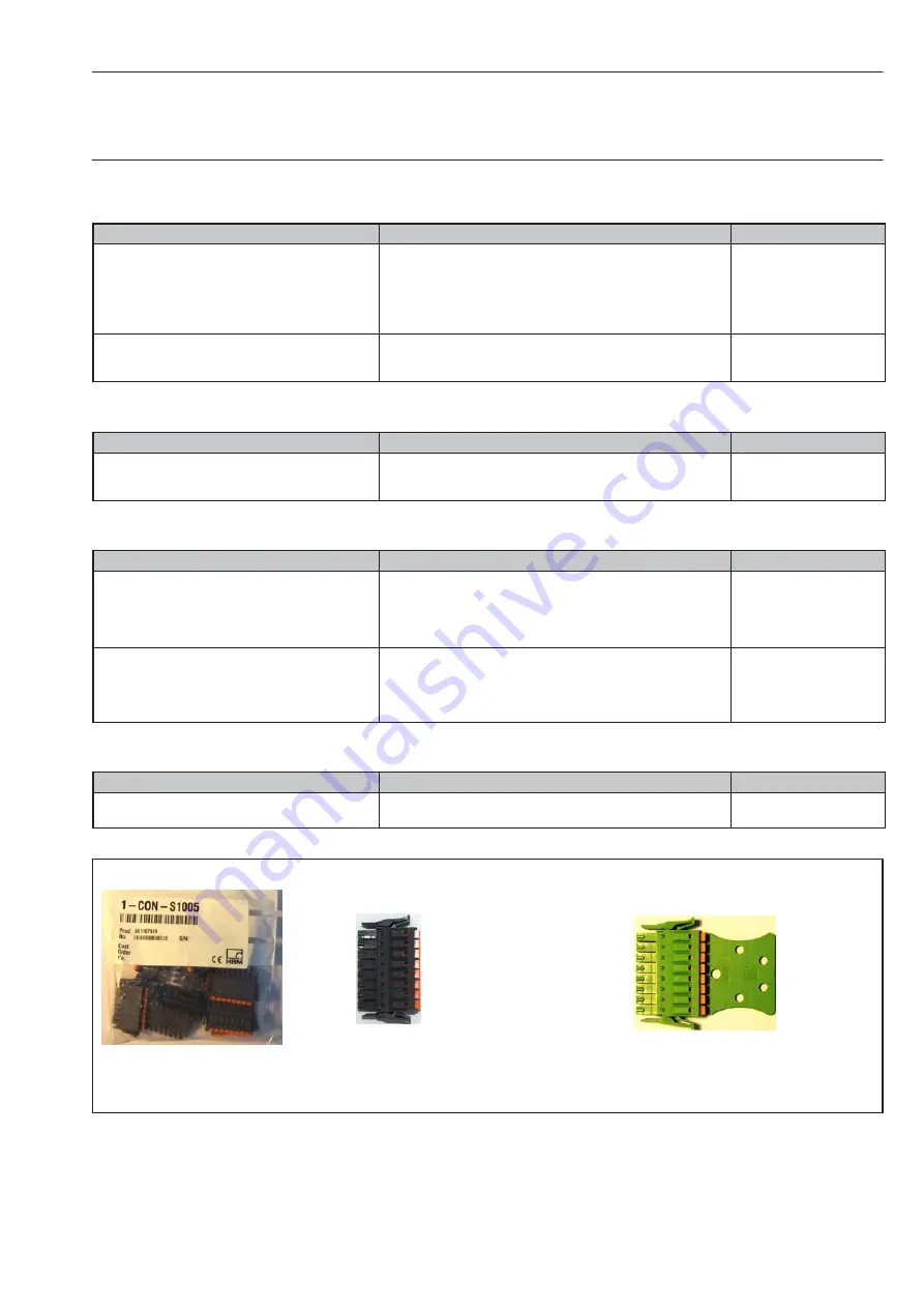
Push-in connectors (8 pins)

10 push-in connectors, Phönix Contact, 8 pins

(Module: MX879, MX1601, MX1615)

1

CON

S1005

Phönix push-in connector

without 

 strain refief

Push-in connectors

Packet comprising 10 push-in terminals

(8 pins)

(directly from HBM, 1

CON

S1005)

Available from Phoenix (http://www.phoenix-

contact.com

)

Type

 : FMC 1,5/ 8-ST-3,5-RF

Order no.: 1952089

Available from Phoenix (http://www.phoenix-

contact.com

):

Type : FMC 1,5/8-STZ3

3,5-RF

Order no. : 1702246

Phönix push-in connector

with

 strain relief

Summary of Contents for QuantumX MX1609

Page 1: ...I3031 8 0 en Operating Manual ...

Page 2: ...d ...

Page 3: ...37 4 4 CASE FIT 39 4 5 BPX001 backplane 40 4 5 1 Connection 41 4 5 2 Wall mounting 42 4 5 3 Mounting the modules 43 4 5 4 Backplane with Ethernet connection 46 4 5 5 Backplane with FireWire connection 47 4 5 6 Synchronizing a system setup with multiple backplanes 48 5 Connecting individual QuantumX modules 49 5 1 Connecting the supply voltage 49 5 2 Connection to host PC or notebook 50 5 2 1 Singl...

Page 4: ...6 4 MX440A universal amplifier 91 6 5 MX410 highly dynamic universal amplifier 92 6 5 1 MX410 pin assignment 93 6 5 2 MX410 status display 94 6 6 MX460 frequency measuring amplifier 95 6 6 1 MX460 pin assignment 96 6 6 2 MX460 status display 97 6 7 MX1609 1609T MX1609P thermocpuples modules 98 6 7 1 Thermocouple with TEDS functionality RFID 100 6 7 2 MX1609 MX1609T status display 101 6 8 MX471 CAN...

Page 5: ...equency measurement without directional signal RS 485 Differential signals 133 6 11 20 Frequency measurement with directional signal RS 485 Differential signals 134 6 11 21 Frequency measurement without directional signal single pole mode 135 6 11 22 Frequency measurement with directional signal single pole mode 136 6 11 23 Pulse counting RS 485 Differential signals 137 6 11 24 Pulse counting sing...

Page 6: ...ule IP20 171 9 3 2 FireWire cable module to module IP65 172 9 3 3 Connection cable PC to module IP20 172 9 4 General information 173 9 4 1 Plug kit with TEDS chip 173 9 4 2 Port saver SubHD 15pol 173 9 4 3 Adapter D Sub HD 15 pin to D Sub 15 pin 174 9 5 MX840 accessories 175 9 5 1 Cold junction for thermocouples 175 9 6 Accessories MX410 176 9 7 MX1609 accessories 177 9 7 1 Thermo connector with i...

Page 7: ...tions This can be done for example by mechanical interlocking error signaling limit value switches etc Safety rules A module must not be connected directly to a power supply network The maximum permissible supply voltage is 10 30 V DC The supply connection as well as the signal and sense leads must be installed in such a way that electromagnetic interference does not adversely affect device functi...

Page 8: ...overs only a small area of measurement technology In addition equipment planners installers and operators should plan implement and respond to the safety engineering considerations of measurement technology in such a way as to minimize remaining dangers Prevailing regulations must be complied with at all times There must be reference to the remaining dangers connected with measurement technology A...

Page 9: ...ho possess the appropriate qualifications for their function This module is only to be installed and used by qualified personnel strictly in accordance with the specifications and the safety rules and regulations This includes people who meet at least one of the three following requirements Knowledge of the safety concepts of automation technology is a requirement and as project personnel you must...

Page 10: ...ch failure to comply with safety requirements can result in death or serious bodily injury Symbol CAUTION Meaning Potentially dangerous situation Warns of a potentially dangerous situation in which failure to comply with safety requirements could result in damage to property or some form of bodily injury Symbol Meaning Electrostatic Sensitive Devices Devices marked with this symbol can be destroye...

Page 11: ...complies with the requirements of the relevant EC directives the declaration of conformity is available at http www hbm com hbmdoc Symbol Meaning Statutory marking requirements for waste disposal National and local regulations regarding the protection of the environment and recycling of raw materials require old equipment to be separated from regular domestic waste for disposal For more detailed i...

Page 12: ...t expose the modules to direct sunlight Comply with the maximum permissible ambient temperatures as stated in the specifications Ensure sufficient ventilation during installation into the BPX001 backplane Maintenance and cleaning The modules are maintenance free Please note the following points when cleaning the housing Before cleaning disconnect the device from all connections Clean the housing w...

Page 13: ...erating manual in PDF format A comprehensive online help with index and easy search options which is available after the installation of a software packet e g QuantumX Assistant catman EASY Here you will also find information for confirming the modules and channels These documents are available on the QuantumX system CD supplied with the instrument S after installation of QuantumX Assistant on you...

Page 14: ...4 individually configurable inputs for connecting HBM torque transducers T10 T40 incremental encoders frequency signal sources and digital signals S MX1609 thermocouple amplifier The module has 16 inputs for type K thermocouples S MX1609 T Thermocouple amplifier The module has 16 inputs for typeT thermocouples S MX1609 P thermocouple amplifier As MX1609 however with IP65 degree of protection S MX8...

Page 15: ...nstallation on an active module carrier not applicable for P variants S Status LEDs for displaying general system and channel states S A working standard calibration certificate has been stored on every amplifier It can be read out via QuantumX Assistant S AutoBoot module configuration is retained With amplifiers the following applies for each measurement channel S Electrical isolation signal inpu...

Page 16: ...untin SSI Incremental encoder Indctive rotary encoder PT100 resistance thermometer Potentiometers Resistance Piezoresistive transducer Current fed piezoelectric transducer IEPE Current 20 mA Voltage LVDT Inductive half bridge Inductive full bridge M X 8 4 0 A M X 4 4 0 A 4 19200 3200 For connecting current fed piezoelectric transducers a Smart Module 1 EICP B 2 is required C X 2 7 M X 1 6 0 1 16 1...

Page 17: ...itted in real time isochronously e g from the signal source to an output analog CAN or EtherCAT bus or to the computation This isochronous real time mode can be activated in parallel to the asynchronous mode The maximum data rate is 4 8 kHz The data for phase delays and the filter tables specified in the respective data sheets should be used for computing phase delays from signal input to signal o...

Page 18: ... once to the actual time If only QuantumX modules are being used internal synchronization is sufficient However if synchronous measurements are to be performed by different measurement systems an external Master must be used for synchronization This is also a requirement if the QuantumX modules are a long distance away from one another and a FireWire connection would be too costly and complex Sync...

Page 19: ...ough this depends on the relevant Ethernet utilization Modules that are in proximity to each other should be synchronized by FireWire If the synchronization source for a module is changed to NTP the system must be restarted once catman EASY software from HBM includes an NTP software package Parameters IP address of the NTP server Threshold in μs from which the time deviation to NTP time is tolerat...

Page 20: ... are automatically synchronized as well The code includes the time the year and optionally the seconds of the current day Comparison of synchronization mechanisms Characteristic FireWire Ethernet NTP EtherCat IRIG B Synchronization with other device types QuantumX only QuantumX MGCplus other interrogators all EtherCAT nodes all IRIG B nodes Max distance between QuantumX modules 5 m 40 m with FireW...

Page 21: ... EtherCAT Synchronizing via NTP with FireWire Synchronizing via NTP without FireWire Time base Time base EtherCat Master Time base Auto Auto NTP server Ethernet switch Auto Auto Auto Auto Auto Auto Auto Auto Time base NTP server NTP NTP NTP Fig 2 1 Different methods of time synchronization CX27 or the module with the highest serial number ...

Page 22: ...en If synchronization is disturbed or not yet established the system LED shows orange System LED Example MX840 Time format used Basis 1 1 2000 Time stamp 64 bit 32 bit seconds 32 bit fractions of a second resolution 1 232 These time stamps are appended to the measured values There are several synchronization methods to choose from also see Fig 2 1 page 21 S synchronizing via FireWire S synchronizi...

Page 23: ...gs Read factory calibration certificate Analysis information status log file Save configuration to operating PC Channels sensors Configuration name connection type TEDS semi automatic assignment Measurement alphanumeric display Open the TEDS editor and read write to TEDS Activate deactivate isochronous operation via FireWire Individual signals Set sampling rate and filter type cut off frequency Me...

Page 24: ...aph indicator table status LED etc Various storage options all data cyclic ring buffer long duration measurement etc Exporting measurement data into commonly used data formats catman BIN Excel ASCII DIADEM MDF Graphical analysis of recorded data Automating measurement sequences AutoSequence and EasyScript Reporting using graphical displays analyses comments The software package consists of various...

Page 25: ... the API you have full access to all QuantumX functions through an individually programmed application e g your own operator interface The API can be used in the form of programming libraries in NET or COM technologies The libraries enable the creation of own applications in programming languages such as e g Visual Basic C C or Delphi Functions such as communication connection configuration of mea...

Page 26: ...26 Software HBM QuantumX Compare your version with the actual firmware version on the Internet under www hbm com quantumX ...

Page 27: ... package from the HBM website Close all open HBM software install the new software and start the QuantumX Firmware Update Click on the Find modules symbol or press the function key F4 Select the module Select the required version in the drop down menu New firmware Activate the modules whose firmware you want to update by checking the boxes in the column Update and then click on the OK button Press...

Page 28: ...es measurement data acquisition using the following QuantumX amplifiers MX840 MX840A MX440A MX410 MX460 and MX1609 Latest information can be found in the corresponding release notes at www hbm com 3 8 DASYLab driver DASYLab is a graphic programming system from the company National Instruments The acronym stands for Data Acquisition System Laboratory The main application areas for DASYLab are in me...

Page 29: ...s data to be recorded visualized and analyzed via the gateways connected to the PC This includes signals from fieldbuses such as FlexRay CAN CAN derivatives or LIN or also from measuring instruments such as QuantumX or from cameras Using special protocols such as CCP or XCP the software enables internal control instrument parameters such as sensor data or parameter tables to be read and if possibl...

Page 30: ...ngs with degree of protection IP20 and in some cases with IP65 as per DIN EN 60529 IP 2 0 IP 6 5 Code index Degree of protection against contact and foreign bodies Code index Degree of protection against water 2 Protection against contact with fingers protection against foreign bodies with 12 mm 0 No water protection 6 Complete protection against contact protection against penetration of dust 5 Pr...

Page 31: ...31 Housings HBM QuantumX Fig 4 2 Amplifier MX1609 P in IP65 housing ...

Page 32: ...OT This also serves for centering when several devices are stacked on top of each other and offers a certain degree of protection against mechanical damage MX840 housing Case protection Cover Fig 4 3 Universal amplifier MX840 with case protection The mounting of the housing clips shown in the following pictures must be implemented on both sides of the housing a f 2 5 Fig 4 4 Removing the CASEPROT ...

Page 33: ...33 Housings HBM QuantumX Cover Fig 4 5 Removing the cover Housing clip a f 2 5 Fig 4 6 Mounting the housing clip ...

Page 34: ...34 Housings HBM QuantumX a f 2 5 Fig 4 7 Mounting the CASEPROT ...

Page 35: ... housing clips on modules with degree of protection IP65 The mounting shown in the following pictures must be implemented on both sides of the housing Cover Fig 4 8 Removing the cover a f 2 5 Housing clip Fig 4 9 Mounting the housing clip ...

Page 36: ...36 Housings HBM QuantumX Fig 4 10 Attaching the covers ...

Page 37: ...umX 4 3 Connecting housings The following pictures show the connection of two IP20 housings The procedure is identical for IP65 housings Press Fig 4 11 Unclip the housing clip Catch Lever Fig 4 12 Unclip the lever and catch ...

Page 38: ...38 Housings HBM QuantumX Fig 4 13 Close the lever Fig 4 14 Connected housings ...

Page 39: ...llows flexible mounting of IP20 protected modules of the QuantumX series A lashing strap or CASE CLIP can be used for fastening the modules Laschen für die zu sätzliche fixierung mit Spanngurten 132 169 5 Ø 5 6 22 11 4 approx 30 Fig 4 15 Mounting of the IP20 version ...

Page 40: ...Wire interfaces of the backplane The FireWire interfaces of the individual modules are actively connected to each other The supply voltage 18 V 30 V DC for the modules must be supplied externally The circuits of the FireWire connections and the modules are protected with a total of four fuses with control displays arrangement see 1 1 The modules can be positioned anywhere in the backplane The back...

Page 41: ... FireWire Fuses with control LEDs 4 x 4 A T Supply voltage 18 V 30 V DC 5 A max Ground VG strip module connection Fig 4 17 BPX001 connections No Protection 1 FireWire X1 connection 2 FireWire X2 connection 3 Slots 1 to 4 4 Slots 5 to 9 1 1 Fuse assignments ...

Page 42: ... BPX001 drilling pattern and dimensions Note the following information when installing one or more backplanes in a control cabinet When installing in a control cabinet the temperature limits given in the technical data of the backplanes must be complied with Depending on the installation situation sufficient ventilation vertical air flow or cooling must be provided the maximum total output on a ba...

Page 43: ... in backplanes in housings with IP20 protection without case protection case clips or lateral covers If these are present remove as shown in Chapter 4 Mounting sequence 1 Remove the cover of the connecting plug rear of module Cover Fig 4 19 Remove cover 2 Unscrew the upper and lower screwed clamping glands of the backplane up to the stop the screws are secured against falling out ...

Page 44: ...ule vertically on the backplane and push it in carefully on the lower guide rail back up to the stop Guide rails Upper screwed clamping gland a f 4 0 Lower screwed clamping gland Fig 4 20 Mounting the module Fig 4 21 Centering above the connection plug ...

Page 45: ...45 BPX001 Backplane HBM QuantumX 4 Tighten the lower then the upper screwed clamping gland 1 2 Fig 4 22 Tightening the screwed clamping glands sequence ...

Page 46: ...ateway enables a BPX backplane to be connected via Ethernet Maximum data throughput 400 kS sec The FireWire sockets on the backplane allow integration of distributed modules into the system FireWire B BPX001 CX27 or BPX001 S31 CX27 Fig 4 23 Anbindung eines Mododulträgers über Ethernet ...

Page 47: ...on The BPX backplane can be directly connected to a PC or data recorder via FireWire The second FireWire socket on the backplane allows integration of distributed modules into the system B BPX001 or BPX001 S31 FireWire Fig 4 24 Anbindung eines Mododulträgers über FireWire ...

Page 48: ...chronizing a system setup with multiple backplanes CX27 gateway modules enable several BPX backplanes to be synchronized CX27 to CX27 connection using KAB272 2 or 5 via FireWire socket on the front Fig 4 25 Synchronisieren mehrerer Modulträger ...

Page 49: ...een battery and module to compensate for voltage drops during starting processes Module Typical power consumption including transducer excitation Watt MX840 13 MX840A 12 MX440A 10 MX1601 13 MX410 15 MX460 9 MX1609 6 MX1609 P 6 CX22 12 CX27 7 MX878 7 MX471 6 If several modules are connected to each other via FireWire for time synchronous data acquisition see Fig 5 4 the supply voltage can be looped...

Page 50: ...ction TCP IP 100 Mbps Cross Over 10 V 30 V DC 1 NTX001 or 1 KAB271 3 X100 X104 Fig 5 2 Single Ethernet connection NOTE You must use an Ethernet crossover cable with older computers Newer PCs laptops have Ethernet interfaces with autocrossing function You can also use Ethernet patch cables here ...

Page 51: ...atch cable 10 V 30 V DC 10 V 30 V DC 10 V 30 V DC Fig 5 3 Multiple connection via Ethernet Modules can be connected to the PC with standard Ethernet switches We recommend patch cables With the star structure displayed here measurement data from other modules is not lost in case of a cable break in the ethernet cable ...

Page 52: ...ious lengths x m Fig 5 4 Example for multiple connection via Ethernet with synchronization The supply voltage for the modules is looped through FireWire in the configuration shown above max 1 1 A through FireWire power consumption for 1 module see specifications in data sheet Advantage of this connection structure The other modules remain active in case of a cable break in the ethernet cable ...

Page 53: ...peer to peer NOTE Ensure that your PC has a valid IP address Install and start up the latest QuantumX Assistant version on your PC All screenshots shown in this quick start guide display the menus in the operating system Windows XP Click on the icon Find modules or press the function key F4 ...

Page 54: ...ded setting Recommended If your modules are not yet displayed click on the button NOTE The network connection can be influenced by w An activated WiFi connection on your PC Switch this connection off and start the network search again w The use of a standard patch cable in a direct connection peer to peer If the module you have selected appears in black in the list immediate operation is possible ...

Page 55: ... Manual configuration Deactivate DHCP and enter the same subnet mask address as used with your PC Change the IP address of your module so that it matches communication see example below Example Manual IP setting module side Settings IP address Subnet mask Module before 169 1 1 22 255 255 255 0 PC Notebook 172 21 108 51 255 255 248 0 Module after 172 21 108 1 255 255 248 0 The first three digit gro...

Page 56: ...ection HBM QuantumX Module settings PC settings Module settings PC settings Automatic Configuration Manual Configuration 255 255 248 0 172 21 108 1 Fig 5 5 Example settings for direct connection of one module ...

Page 57: ...n outs can be found in the operating manual Channel configuration can be found in the online help of the software Ethernet settings adapt your PC s IP address If you use your computer in various networks IP address changes but your modules have a fixed IP address you should use the Alternative Configuration in the TCP IP properties fixed IP address and subnet mask user defined Edit the PC settings...

Page 58: ... the option User defined and enter your data in the IP address line and subnet mask Example Manual IP setting PC side Settings IP address Subnet mask Module before 169 1 1 22 255 255 255 0 PC Notebook 172 21 108 51 255 255 248 0 PC Notebook after 169 1 1 1 255 255 255 0 ...

Page 59: ...ration for the direct connection Integrating modules in an Ethernet Network Activate the checkbox DHCP and click on OK the following confirmation window then appears Confirm the settings with the Yes button the module is then restarted with the current settings After approx 45 seconds click on the button ...

Page 60: ...ht up green if not please check your network settings again If the network settings are ok the module names are shown in black Mark the relevant modules by checking the relevant checkbox Confirm with OK Channel configuration can be found in the online help of the software ...

Page 61: ...ion S Data synchronization S Supply voltage via FireWire connection cable max 1 5 A 10 V 30 V DC 1 NTX001 or 1 KAB271 3 1 KAB270 3 Adapter PC PCI or PCIe card Notebook PC card previously PCMCIA X102 X104 Fig 5 6 Single FireWire connection NOTE Please check in advance whether a firmware or software update is required Software firmware downloads can be found on the HBM website www hbm com downloads ...

Page 62: ...ion 1 Kab269 2 5 2 m connection cable 1 Kab269 0 2 0 2 m connection cable Fig 5 7 Example for multiple connection via FireWire with synchronization Data are transferred modules are synchronized in timing and voltage is supplied via the FireWire connections You can connect a maximum of 12 modules in series with each other NOTE Different voltage sources need to supply the same voltage level ...

Page 63: ...63 Connection HBM QuantumX 5 2 7 Setup with CX22 W data recorder FireWire connection 10 V 30 V DC e g NTX001 Fig 5 8 Setup with CX27 ...

Page 64: ...64 Connection HBM QuantumX 5 2 8 MX840A universal amplifier with CAN output The measurement signals of connectors 2 8 are output to CANbus via connector 1 Fig 5 9 MX840A with CAN output ...

Page 65: ...9 Output of the inputs of several measurement modules via CANbus Isochronously parameterized signals can be output The parameterization is permanently stored in the modules EEPROM dbc 4x MX471 KAB269 KAB269 Fig 5 10 Output via CANbus ...

Page 66: ...signals with normalized voltage Isochronously parameterized signals can be output The parameterization is permanently stored in the modules EEPROM 8 scaled voltage outputs 200 signals 4 8 kS sec channel KAB269 KAB269 MX KAB269 Fig 5 11 Analog output in real time ...

Page 67: ...t data rates and filters For example the first signal of an input channel with a high data rate e g acceleration sensor with 96 000 measured values per second and deactivated filter 38 kHz maximum bandwidth can be output to PC software for analysis while the second signal with 4 800 measured values per second and 600 Hz filter can be output via CAN or EtherCAT KAB269 CX27 Fig 5 12 Real time output...

Page 68: ...is confirmed acoustically by Windows Whenever you connect a new module via FireWire to your computer the operating system will prompt you to register the module Always refer here to the driver hbm1394 sys Install and then start the latest QuantumX Assistant on your PC Click on the icon Find modules or press the function key F4 The field Modules found displays all modules connected via FireWire If ...

Page 69: ...d via FireWire this may be caused by the following The modules have not been properly registered Click on the FireWire driver in Systray check the driver behind the modules and reinstall it if necessary hbm1394 sys Check all connections between the modules ...

Page 70: ...different firmware version Your PC software must also be updated When you want to update the firmware of your module to improve its performance Use QuantumX Assistant as follows to determine which firmware version your module is working with Right click on Module Details System parameters Compare your version with the latest firmware version on the Internet under www hbm com quantumX ...

Page 71: ...ware updater in most cases C Programs HBM QuantumX Firmware Update Download Click on the Find modules symbol or press function key F4 see chapter 2 1 Select the module Select the required version in the dropdown menu New firmware Activate the modules whose firmware you want to update by checking the boxes in the column Update and then click on the OK button Click on the Start button and wait until...

Page 72: ...ules maximum 24 you must use hubs Hubs are devices that connect network chains together in star configurations This connection mode is again limited to 14 hops A hop is the transition from one module to another this means n 1 hops for n QuantumX modules in a chain Depending on the connection situation 1 to 2 hops are counted in one hub see Fig 5 14 To count the total number of hops the longest cha...

Page 73: ...rt 3 Port 4 1 Hop Connection to Port 1 and or 2 Port 4 2 Hops Port1 Phy 1 Phy 2 Port 1 Port 2 Port 3 Port 4 Port2 Port3 Port4 Fig 5 14 Connection situation at AVT 1394b hub Note Always connect the chain with the most modules to Port 3 or Port 4 ...

Page 74: ...e bridged with opto hubs that enable distances of up to 500 m with the use of a glass fiber cable 1 2 1 2 3 4 5 1 Opto Hub 6 Opto Hub Max 500 m 1 Hop P3 P4 P4 P3 7 8 Displayed Total number of modules 11 Total number of hops 8 QuantumX module Longest chain to data sink Fig 5 15 Example for the use of opto hubs ...

Page 75: ...75 Connection HBM QuantumX 5 2 16 FireWire with opto hub and glass fiber cable Opto Hub Opto Hub 10 V 30 V DC Glass fiber cable Max length 500 m Fig 5 16 FireWire and glass fiber cable ...

Page 76: ... required electromagnetic immunity or susceptibility EMS and permitted electromagnetic interference EMI has become increasingly more important over the past years The HBM Greenline shielding design The complete measuring chain is fully enclosed in a Faraday cage through the unique design of the cable shield The cable shield is flattened connected to the transducer housing and routed to the amplifi...

Page 77: ...conductor In the case of potential differences in the measuring system a potential equalization conductor has to be laid recommended very flexible stranded wire 10 mm2 line diameter Ensure that signal and data lines are run separately from current carrying power lines Ideally use metal cable ducts with internal separating plate Signal ground earth and shield should be separate from one another To ...

Page 78: ...2 1 8 Hsg 9 Supply voltage 5V 24V1 Power supply 0V 4 1 Adjustable via software Cable shield Sensor 3 kΩ Connection as per measurement principle Hsg housing CAUTION The output voltage during idling is up to 20 higher than set when the voltage 8 V If a current of 2 mA is drawn the voltage falls back to the set value The condition is met in sensors with a power consumption of min 20 mW This can also ...

Page 79: ... V for bridge transducers for example S The linear characteristics as the relation between the measured quantity and the electrical signal S If applicable the transducer s required excitation and electrical power supply Additional information that can be read out using corresponding software for example S Transducer manufacturer type serial number etc S Calibration date recalibration interval cali...

Page 80: ... patented zero wire circuit After digital communication data mode the amplifier switches to the measurement mode The U93 force transducer is an example for such a transducer S Thermocoulpe amplifiers with an RFID chip integrated in the transducer plug use TEDS technology for example to electronically connect the measuring point with the transducer The data sheet to the respective amplifier provide...

Page 81: ...ic Data Sheet The amplifier uses a serial 1 wire interface for communication with this EEPROM reads out the data sheet and configures the amplifier accordingly Retrofilling TEDS in the plug is shown in the figure below HBM empfiehlt den TEDS Baustein 1 Wire R EEPROM DS24B33 von Dallas Maxim Um diesen Chip lesen und beschreiben zu können ist mindestens Firmware Version 1 21 16 2 21 16 sowie mindest...

Page 82: ...ansmitted to the A D converter zero and reference signal MX840 MX840A and MX440A amplifiers offer an auto adjustment function In the full half bridge measurement mode these amplifiers use a second measuring circuit that measures in parallel to the input circuit and carries out a calibration cycle at 30 second intervals Long term and short time stability are thus guaranteed in this circuit A patent...

Page 83: ...n from the supply voltage of the amplifier is not required MX840 connectable transducers Transducer type Connector sockets see page Full bridge strain gauges 1 8 112 Inductive transducers 1 8 113 Inductive transducers 1 8 116 Quarter bridge via Adapter 1 8 LEERER MERKER LVDT 1 8 121 Voltage 1 8 125 126 Current 1 8 127 Current fed piezoelectric transducer IEPE ICP 1 8 122 Piezoresistive transducer ...

Page 84: ...84 Connection HBM QuantumX MX840 connectable transducers continued Torque rotary speed 5 8 134 135 Frequency measurement pulse counting 5 8 from 133 CANbus 1 143 ...

Page 85: ...ith Pin 9 Plug identification 5 Measurement signal potentiometer measurement signal voltage input 100 mV f1 signal differential SSI data 6 TEDS ground frequency measurement 7 Sense lead f2 signal differential CAN High SSI clock 8 Sense lead f2 signal differential CAN Low SSI clock 9 Signal ground 10 Measurement signal f1 signal differential SSI data 11 Active sensor supply 5 24 V 0 V 12 Active sen...

Page 86: ...ware download active system is not ready Orange Connection newly assigned transducer identification running calibration Green Error free operation Ignore TEDS or if available set channel is manually configured Flashing green 5s then green Reading TEDS data Flashing orange 5s then green Manual configuration running ignore TEDS Red No sensor connected Channel error incorrectly parameterized connecti...

Page 87: ... see page Full bridge strain gauges 1 8 112 Inductive transducers 1 8 113 Half bridge strain gauges 1 8 115 Inductive transducers 1 8 116 Quarter bridge via Adapter 1 8 LEERER MERKER LVDT 1 8 121 Voltage 1 8 125 126 Current 1 8 127 Current fed piezoelectric transducer IEPE ICP 1 8 122 Piezoresistive transducer 1 8 114 Resistance 1 8 129 Potentiometers 1 8 120 PT100 PT1000 resistance thermometers 1...

Page 88: ...88 Connection HBM QuantumX MX840A connectable transducers continued Frequency measurement pulse counting 5 8 from 133 Pulse width modulation PWM 5 8 133 Torque Rotational speed 5 8 134 135 CANbus 1 143 ...

Page 89: ...ification 5 Measurement signal potentiometer measurement signal voltage input 100 mV f1 signal differential SSI data 6 TEDS ground frequency measurement 7 Sense lead f2 signal differential CAN High SSI clock 8 Sense lead f2 signal differential CAN Low SSI clock 9 Signal ground 10 Measurement signal f1 signal differential SSI data 11 Active sensor supply 5 24 V 0 V 12 Active sensor supply 5 24 V 13...

Page 90: ...mware download active system is not ready Orange Connection newly assigned transducer identification running calibration Green Error free operation Ignore TEDS or if available set channel is manually configured Flashing green 5s then green Reading TEDS data Flashing orange 5s then green Manual configuration running ignore TEDS Red No sensor connected Channel error incorrectly parameterized connect...

Page 91: ... transducers are connected via 15 pin D SUB 15HD device connectors All measuring channels are electrically isolated von one another and from the mains The transducer types that can be connected and the status display are identical to those of the MX840A universal amplifier see page 87 System LED Connection LED Fig 6 6 MX440A front view ...

Page 92: ...ically isolated von one another and from the mains When using the adjustable transducer excitation electrical isolation from the supply voltage of the amplifier is not required MX410 Connectable transducers Transducer type Connector sockets see page Full bridge strain gauges 1 40 112 Inductive transducers 1 4 113 Inductive transducers 1 4 116 Half bridge strain gauges 1 4 115 Quarter bridge via Ad...

Page 93: ... voltage 4 Always connect with Pin 9 Plug identification 5 Measurement signal 6 TEDS 7 Sense lead 8 Sense lead 9 Signal ground 10 Measurement signal 11 Active sensor supply 12 Active sensor supply 13 Current input 30 mA 14 Voltage input 10 V IEPE 15 Reset external charge amplifier The analog output can be tapped via BNC Please see chapter 7 Functions and outputs for information about the configura...

Page 94: ...ration Green Error free operation Ignore TEDS or if available set channel is manually configured Flashing green 5s then green Reading TEDS data Flashing orange 5s then green Manual configuration running ignore TEDS Red No sensor connected Channel error incorrectly parameterized connection error invalid TEDS data Red Sensor supply overload Analog output LEDs Green Error free operation Ignore TEDS o...

Page 95: ...trically isolated von one another and from the mains When using the adjustable transducer excitation electrical isolation from the supply voltage of the amplifier is not required MX460 connectable transducers Transducer type Connector sockets see page Torque rotary speed 1 4 134 Frequecy mesurement pulse counting 1 4 from 133 Puls width Pulse duration Period duration 1 4 133 Passive inductive rota...

Page 96: ...9 Pin arrangement of connection plug view from the solder side Pin Connection 1 TEDS 2 Reference pulse 0 zeroing pulse 3 Reference pulse 0 zeroing pulse 4 Always connect with Pin 9 Plug identification 5 Frequency input f1 6 TEDS signal ground 7 Frequency input f2 8 Frequency input f2 9 Reference voltage Vref 2 5 V 10 Frequency input f1 11 Active sensor supply 5 24 V 12 Active sensor supply 5 24 V ...

Page 97: ...All LEDs are flashing orange Firmware download active system is not ready Orange Connection newly assigned transducer identification running calibration Green Error free operation Ignore TEDS or if available set channel is manually configured Flashing green 5s then green Reading TEDS data Flashing orange 5s then green Manual configuration running ignore TEDS Red No sensor connected Channel error i...

Page 98: ...rmocouples Co CoNi can be connected to the module MX1609T for measuring temperatures MX1609 MX1609T MX1609P connectable transducers Transducer type Connector sockets see page Thermocouple type K type T 1 16 131 MX1609 Type Thermocouple material 1 Thermocouple material 2 K Nickel chrome color code green Nickel aluminum color code white Thermocouple T Copper color code brown Copper Nickel color code...

Page 99: ...99 Connection HBM QuantumX Connection of the thermocouple plug in the miniature design ...

Page 100: ...s and mounting conditions to be minimized The MX1609 processes a maximum of 64 pairs of values The Calibration Table TEDS template enables 14 pairs of values to be saved if no additional optional templates are being used This function provides the best results when the ambient temperature of the MX1609 and thus the temperature of the cold junction is kept constant Conditions for using RFID chips f...

Page 101: ...tem is not ready Orange Connection newly assigned transducer identification running calibration Green Error free operation Ignore TEDS or if available set channel is manually configured Flashing green 5s then green Reading TEDS data Flashing orange 5s then green Manual configuration running ignore TEDS Red No sensor connected Channel error incorrectly parameterized connection error invalid TEDS da...

Page 102: ...r as sender gateway Parameterization as receiver is described in chapter 6 8 3 Parameterization as sender is described in chapter 7 The online help coming with the respective software package provides detailed information about parameterization Note To ensure normal operation the CANbus needs to be terminated at both ends and only there using appropriate termination resistors A 120 ohm termination...

Page 103: ...umX 6 8 2 MX471 pin assignment 1 5 6 9 Fig 6 12 Pin arrangement of connection plug view from the solder side Pin Connection 1 no function 2 CAN Low 3 GND 4 no function 5 CAN Shield 6 GND 7 CAN High 8 no function 9 no function ...

Page 104: ... into the sensor database Should a CAN database not be available it can be generated by the user Editors for this purpose are provided by different companies Received CAN messages are instantly time stamped in the measurement mode This enables directly acquired measured quantities and CAN messages to be acquired and analyzed in parallel and synchronously in the entire system Note MX471 is not a cl...

Page 105: ...ellow flickering Intermittent bus errors Warning and CAN activity Constant yellow Intermittent bus errors Warning and no CAN activity Red on Bus error CAN interface in Bus OFF status CAN LEDs Channel Green flickering No bus error and CAN activity Constant green No bus error and no CAN activity Yellow flickering Intermittent bus errors Warning and CAN activity Constant yellow Intermittent bus error...

Page 106: ...minal connectors Phoenix Contact FMC 1 5 8 ST 3 5 RF order no 1952089 All measuring channels are electrically isolated von one another and from the mains When using the adjustable transducer excitation electrical isolation from the supply voltage of the amplifier is not required MX1601 connectable transducers Transducer type MX1601 connectable transducers see page Voltage 1 16 125 126 Current 1 16...

Page 107: ...ignment of the connector plug view from the connection side Pin Connection 1 Voltage input 10 V 100 mV IEPE 2 Signal ground TEDS 3 Current input 20 mA 4 TEDS 5 Always connect with Pin 2 Plug identification 6 Active sensor supply 7 Active sensor supply 8 Housing shield connection NOTE The transducer excitation voltage can be set in the range of 5 24 V and is only available at channels 1 8 At channe...

Page 108: ...or Connection LEDs All LEDs are orange Boot procedure running system is not ready All LEDs are flashing orange Firmware download active system is not ready Orange Connection newly assigned transducer identification running calibration Green Error free operation Ignore TEDS or if available set channel is manually configured Flashing green 5s then green Reading TEDS data Flashing orange 5s then gree...

Page 109: ... excitation constant DC voltage or 1200 Hz AC square wave carrier frequency of 0 5 V 1 V 2 5 V or 5 V When TEDS or T ID is used the measurement channel is automatically parameterized after connection MX1615 connectable transducers Transducer type Connector sockets see page Full bridge strain gauges 1 16 112 Half bridge strain gauges 1 16 115 Quarter bridge strain gauges 1 16 115 Voltage 1 16 125 1...

Page 110: ... be completed only in the event of voltage measurements If this bridge is missing no measurement values will be recorded at the connection 1 2 3 4 5 6 7 8 1 2 3 1 Wire EEPROM Maxim DS2433 Bottom view 2 Data 3 no function Bridge 1 Fig 6 15 Pin assignment of the connector plug view from the connection side Pin Connection 1 TEDS 2 Bridge excitation voltage 3 Sense lead 4 Bridge excitation voltage 5 S...

Page 111: ...ror Connection LEDs All LEDs are orange Boot procedure running system is not ready All LEDs are flashing orange Firmware download active system is not ready Orange Connection newly assigned transducer identification running calibration Green Error free operation Ignore TEDS or if available set channel is manually configured Flashing green 5s then green Reading TEDS data Flashing orange 5s then gre...

Page 112: ...8 7 4 9 wh bk rd bu gn gy ye 1 2 4 3 Measurement signal Excitation Sense lead Sense lead Excitation Measurement signal Cable shield 10 Hsg 2 3 5 Cable color code wh white bk black bu blue rd red ye yellow gn green gy gray Hsg housing 1 5 6 10 11 15 6 1 1 2 3 1 wire EEPROM view from below 2 Data 3 No function 1 1 8 Push in 6 4 2 7 8 3 5 1 MX1615 ...

Page 113: ...440A MX410 8 7 4 9 wh bk rd bu gn gy ye 2 4 Measurement signal Excitation Sense lead Sense lead Excitation Measurement signal Cable shield 10 Hsg 2 3 5 Cable color code wh white bk black bu blue rd red ye yellow gn green gy gray Hsg housing 1 5 6 10 11 15 6 1 1 2 3 1 wire EEPROM view from below 2 Data 3 No function 1 1 3 ...

Page 114: ...ules MX840 MX840A MX440A MX1615 5 8 10 7 1 2 4 3 Measurement signal Excitation Sense lead Sense lead Excitation Measurement signal Cable shield 2 3 Hsg 4 9 Hsg housing 6 1 1 2 3 1 wire EEPROM view from below 1 5 6 10 11 15 2 Data 3 No function 1 1 8 Push in 6 4 2 7 8 3 5 1 MX1615 ...

Page 115: ...7 4 9 Hsg 2 3 5 Cable color code wh white bk black bu blue rd red ye yellow gn green gy gray wh bk bu gn gy ye Measurement signal Excitation Sense lead Sense lead Excitation Cable shield Hsg housing 1 5 6 10 11 15 6 1 1 2 3 1 wire EEPROM view from below 2 Data 3 No function 1 1 8 Push in 6 4 2 7 8 3 5 1 MX1615 ...

Page 116: ...40A MX410 8 7 4 9 Hsg 2 3 5 Cable color code wh white bk black bu blue rd red ye yellow gn green gy gray wh bk bu gn gy ye Measurement signal Excitation Sense lead Sense lead Excitation Cable shield Hsg housing 6 1 1 2 3 1 wire EEPROM optional view from below 1 5 6 10 11 15 2 Data 3 No function 1 ...

Page 117: ...the MX840 MX840A MX440A and MX410 universal amplifiers see chapter 6 11 7 Hsg housing 2 Data 3 No function 1 1 8 Push in 4 7 1 1 2 3 Vierleiter Anschluss Dreileiter Anschluss 8 Cable shield Excitation Sense lead Sense lead 5 6 SG SG 1 wire EEPROM optional view from below Cable color code bk black bu blue ye yellow gn green gy gray Excitation gy bk bu ye gn ...

Page 118: ... gauges in three wire configuration an adapter can be plugged onto the following modules MX840 MX840A MX440A MX410 Available adapters Strain gauge with 120 ohm order number SCM SG120 Strain gauge with 350 ohm order number SCM SG350 2 1 1 Strain gauge 120 350 See leaflet QuantumX SCM SG120 350 for technical details ...

Page 119: ...hield 2 3 Hsg 4 9 1 2 4 3 RB 2 on transducer Hsg housing 1 5 6 10 11 15 We recommend this connection technique for very small measurement ranges in particularly disturbed environments and when using long cables This applies for all bridge connections With cable lengths 50 m a resistor with half the value of the bridge resistance RB 2 must be connected in each sense lead of the transducer ...

Page 120: ...s Supported by modules MX840 MX840A MX440A 5 8 7 Measurement signal Bridge excitation voltage Sense lead Sense lead Bridge excitation voltage Cable shield1 2 3 Case 4 9 1 2 3 6 1 1 2 3 1 wire EEPROM optional view from below 1 5 6 10 11 15 2 Data 3 No function 1 ...

Page 121: ...orted by modules MX840 MX840A MX440A 8 7 4 9 Hsg 2 10 5 Measurement signal Sense lead Sense lead Excitation Cable shield Measurement signal LVDT transducer Excitation 3 Hsg housing 6 1 1 2 3 1 wire EEPROM view from below 1 5 6 10 11 15 2 Data 3 No function 1 ...

Page 122: ...E means Integrated Electronics Piezo Electric ICP is a registered trademark of PCB Piezotronics Is supported by the following modules MX410 direct to SubHD or via BNC adapter MX1601 directly to the connector MX840 MX840A MX440A with 10 V analog input and 24 V supply via a Smart module 14 Hsg 9 4 Cable shield Option BNC adapter 1 IEPE MX410 Hsg housing 1 5 6 10 11 15 IEPE 1 8 Push in 5 2 1 8 MX1601...

Page 123: ... EEPROM optional view from below Hsg housing Maximum input voltage to housing and signal ground 60 V Accessories for connecting the Smart module Product Description Order No Smart module External 24 V signal conditioning module supplying IEPE with constant current BNC socket and feeding standardized 10 V voltage signal 1 EICP B 2 Connection cable Cable between Smart module and SubHD plug 1 SAC EXT...

Page 124: ...ead and to automate channel configuration according to the IEPE transducer TEDS Editor enables settings to be made S TEDS specific settings f High Level Voltage Output Sensor f Physical Measurand Acceleration m2 s or g f Electrical range standard 10 V f Power requirements required S Complete the data sheet according to the transducer S Excitation level 24 V nominal CAUTION Replacing the IEPE trans...

Page 125: ...1601 module see chapter 6 9 1 10 4 Hsg 5 9 Cable shield U Hsg Housing 6 1 1 2 3 1 5 6 10 11 15 2 Data 3 No function 1 1 wire EEPROM optional view from below 1 8 Push in 1 2 4 5 8 Maximum input voltage to housing and signal ground MX840 MX840A MX440A 60 V MX1601 40 V Adjustable sensor supply 5 V 24 V 0 V Pin 12 Pin 11 Pin 6 Pin 7 MX1601 ...

Page 126: ...ly voltage zero Hsg Housing 6 1 1 2 3 1 5 6 10 11 15 2 Data 3 No function 1 1 wire EEPROM optional view from below 1 8 Push in 6 4 5 7 8 1 MX1615 1 8 Push in 1 5 2 8 4 MX1601 Maximum input voltage to housing and signal ground MX840 MX840A MX440A 60 V MX1601 40 V Adjustable sensor supply 5 V 24 V 0 V Pin 12 Pin 11 Pin 6 Pin 7 MX840 MX840A und MX440A Two measuring ranges 10 V or 60 V can be selected...

Page 127: ...A MX410 MX1601 Pin assignment for the MX1601 module see chapter 6 9 1 13 4 Hsg 9 Cable shield Hsg housing 6 1 1 2 3 1 wire EEPROM view from below 1 5 6 10 11 15 2 Data 3 No function 1 I 1 8 Push in 2 5 3 8 4 Adjustable sensor supply 5 V 24 V 0 V Pin 12 Pin 11 Pin 6 Pin 7 MX1601 Maximum current 30 mA ...

Page 128: ...sg housing I 13 11 Geh 12 9 4 1 5 6 10 11 15 1 8 Push in 6 7 2 8 4 5 3 6 1 1 2 3 1 wire EEPROM view from below 2 Data 3 No function 1 MX1601 Adjustable sensor supply 5 V 24 V 0 V Pin 12 Pin 11 Pin 6 Pin 7 Maximum current 30 mA The sensor supply needs to be connected in series However this eliminates the electrical isolation from the module supply This applies for MX840A MX840 MX410 and MX440A ...

Page 129: ...ire circuit Excitation Measurement signal 1 Measurement signal 10 4 9 1 When connecting a two wire sensor wire bridges must be soldered in the connector between measurement line and supply 2 5 3 ϑ Hsg housing 6 1 1 2 3 1 wire EEPROM optional view from below 1 5 6 10 11 15 2 Data 3 No function 1 1 8 Push in 4 5 8 6 7 1 MX1615 ...

Page 130: ...les PT100 PT1000 MX840 MX840A MX440A PT100 MX1615 2 Hsg Excitation Cable shield Four wire circuit Excitation Measurement signal Measurement signal 10 4 9 2 5 3 ϑ Hsg housing 6 1 1 2 3 1 wire EEPROM optional view from below 1 5 6 10 11 15 2 Data 3 No function 1 1 8 Push in 4 5 8 6 7 1 MX1615 ...

Page 131: ...erial 2 J Iron Copper Nickel K Nickel chrome color code green Nickel aluminum color code white T Copper Copper nickel S Rhodium platinum 10 Platinum E Nickel chrome Copper nickel B Rhodium platinum 30 Rhodium platinum 6 N Nickel chrome silicone1 Nickel silicone R Rhodium platinum 13 Platinum Thermocouple 1 THERMO MX BOARD soldered into connector plug and contains a cold spot compensation element a...

Page 132: ...RMO MX BOARD in the correct position between the plug pins Note Check the position with the plug shape see picture above In this position the PT1000 of the cold spot compensation element is on top PT1000 Solder the connector pins to the connections on the board PIN 1 TEDS PIN 6 TEDS PIN 5 Thermocouple PIN 10 Thermocouple PIN 9 Signal ground PIN 7 PT1000 cold junction PIN 8 PT1000 cold junction PIN...

Page 133: ...lue rd red ye yellow gn green gy gray 10 f1 Ground Connector 1 Md Cable shield f1 5 1 4 rd wh gy 9 5 V f1 f1 200 mV Schematic diagram 0 V Hsg housing 6 1 1 2 3 1 wire EEPROM view from below 1 5 6 10 11 15 2 Data 3 No function 1 Adjustable sensor supply Pin 12 5 V 24 V 0 7 W per channel 2 W in total More informations see datasheet Pin 11 0 V HBM torque transducer Signal level TTL only Voltage suppl...

Page 134: ...8 6 3 1 7 bk and bu wh gn rd gy f1 f2 f2 8 6 5 f1 Measurement signal speed 0 f1 Measurement signal speed 0 f2 Measurement signal speed 90 f2 Measurement signal speed 90 5 V f1 f1 200 mV Schematic diagram 0 V Hsg housing 6 1 1 2 3 1 wire EEPROM view from below 1 5 6 10 11 15 2 Data 3 No function 1 Adjustable sensor supply Pin 12 5 V 24 V 0 7 W per channel 2 W in total More informations see datashee...

Page 135: ... wh white bk black bu blue rd red ye yellow gn green gy gray 10 Ground Connector 1 Md Cable shield f1 5 1 4 rd wh gy 5 6 5 V 3 5 V 1 5 V Thresholds Thresholds f 1 Schematic diagram Single pole mode 0 V Hsg housing HBM torque transducer 6 1 1 2 3 1 wire EEPROM optional view from below 1 5 6 10 11 15 2 Data 3 No function 1 Adjustable sensor supply Pin 12 5 V 24 V Pin 11 0 V ...

Page 136: ...MX840 MX840A MX440A MX460 10 8 Industrial pulse generator f2 f1 6 4 5 7 9 5 V 3 5 V 1 5 V Thresholds Thresholds f 1 Schematic diagram single pole mode 0 V Hsg Cable shield Hsg housing 6 1 1 2 3 1 wire EEPROM optional view from below 1 5 6 10 11 15 2 Data 3 No function 1 Adjustable sensor supply Pin 12 5 V 24 V Pin 11 0 V ...

Page 137: ...840A MX440A MX460 3 7 5 8 Industrial pulse generator f1 f1 Zeroing pulse Zeroing pulse f2 f2 2 10 9 4 6 5 V f1 f1 200 mV Schematic diagram 0 V Hsg Cable shield Hsg housing 6 1 1 2 3 1 wire EEPROM optional view from below 1 5 6 10 11 15 2 Data 3 No function 1 Adjustable sensor supply Pin 12 5 V 24 V Pin 11 0 V ...

Page 138: ... 6 10 8 3 Industrial pulse generator f2 Zeroing pulse 9 4 7 2 5 5 V 3 5 V 1 5 V Thresholds Thresholds f 1 Schematic diagram Single pole mode 0 V f1 Hsg Cable shield Hsg housing 6 1 1 2 3 1 wire EEPROM optional view from below 1 5 6 10 11 15 2 Data 3 No function 1 Adjustable sensor supply Pin 12 5 V 24 V Pin 11 0 V ...

Page 139: ...col 1 Supported by modules MX840 MX840A MX440A 9 4 Hsg 10 7 f1 Ground SSI Cable shield f1 f2 f2 8 6 5 f1 Data f1 Data f2 Shift clock f2 Shift clock 1 Schematic diagram Hsg housing 1 5 6 10 11 15 Adjustable sensor supply Pin 12 5 V 24 V Pin 11 0 V ...

Page 140: ...der1 Supported by module MX460 9 4 Hsg 14 Ground Cable shield f1 AC 6 Hsg housing 6 1 1 2 3 1 wire EEPROM view from below 1 5 6 10 11 15 2 Data 3 No function 1 Adjustable sensor supply Pin 12 5 V 24 V Pin 11 0 V Maximum input voltage to housing and signal ground 60 V ...

Page 141: ... duration Period duration differential signals Supported by module MX460 6 10 Transducer 9 4 f1 Hsg Cable shield Hsg Housing 6 1 1 2 3 1 wire EEPROM view from below 1 5 6 10 11 15 2 Data 3 No function 1 Adjustable sensor supply Pin 12 5 V 24 V Pin 11 0 V f1 5 ...

Page 142: ...e duration Period duration single pole mode Supported by module MX460 6 10 Transducer 9 4 7 2 5 f1 Hsg Cable shield Hsg Housing 6 1 1 2 3 1 wire EEPROM view from below 1 5 6 10 11 15 2 Data 3 No function 1 Adjustable sensor supply Pin 12 5 V 24 V Pin 11 0 V ...

Page 143: ...ly Pin 12 5 V 24 V does not apply for MX471 Pin 11 0 V MX471 Chanel 1 SubHD 15pol MX840 MX840A 7 2 1 5 6 SubD 9pol 9 8 CAN Low 6 Note Ensure correct termination with termination resistors is made as shown in Fig 6 1 The MX840 does not have any termination the MX471 features internal termination that can be activated by software Node 1 Node n Termination resistance 120Ω Termination resistance 120Ω ...

Page 144: ......

Page 145: ...mple an actual measurement signal additionally scaled filtered or the result of a mathematics function Measurement channels that are used in mathematics functions or directly for analog outputs need to be activated for isochronous data transfer e g in the QuantumX Assistant software Signals tab Note The module configuration is immediately active after system reboot Auto Startup No operating PC is ...

Page 146: ...t at the analog output and made available to the QuantumX system This also makes the signals visible to the software The device parameterization is implemented by the software e g QuantumX Assistant or catman AP Keep in mind the following notes when working with peak monitor channels S The maximum output sample rate is restricted to 4800 Hz S Resetting of PEAK values only via PC software system in...

Page 147: ... continuously updated S HOLD last peak value will be frozen S PEAK peak detection enabled S FOLLOW peak detection disabled i e the channel yields the original signal of the input channel The following combinations are possible Graph for MAX PEAK RUN Graph for MAX PEAK HOLD Graph for MAX Follow HOLD This also applies to the minimum values Graph for Peak Detection Measuring signal Output t Vi Vo Hol...

Page 148: ...nel signal and T the time window in ms Keep in mind the following notes when working with RMS channels S The maximum sample rate is restricted to 4800 2400 Hz S The output sample rate of the RMS channel must not be higher than the sample rate of the input channel S Filters set for the MX410 do not apply to RMS channels These channels are always unfiltered However the input signal is filtered ...

Page 149: ...0 front view MX460 Math channels Keep in mind the following notes when working with these channels S The maximum sample rate is restricted to 4800 2400 Hz S The sample rate of the channel must not be higher than the sample rate of the input channel S Filters set for the MX460 do not apply to math channels These channels are always unfiltered However the input signal is filtered ...

Page 150: ...ut the signal passes through an output characteristic curve parameterized by the user 2 point scaling and a filter also parameterized by the user In addition the rate for DAC is reduced to 96 kS s through interpolation MX878 Math channels The MX878 is a dedicated module designed for analog output and math channels The MX878 supports 4 math channels and 4 peak detection channels In contrast to othe...

Page 151: ... to 2400 Hz S The sample rate of the channel must not be higher than the sample rate of the input channels S Filters do not apply to math channels These channels are always unfiltered Matrix computation function The MX878 enables 4 parallel matrix computations each with a maximum of 6 input and output quantities and 36 constants to be performed Generic formula Fx a1 Ufx a2 Ufy a3 Ufz a4 Umx a5 Umy...

Page 152: ... in mind the following notes when working with peak monitor channels S The maximum sample rate is restricted to 4800 Hz S The sample rate of the peak monitor channel must not be higher than the sample rate of the input signal S The peak units do not accept other peak units or RMS as input Each peak detection unit can monitor either the Min or the Max of one of 4 signals visible as isochronous with...

Page 153: ...use up significant computing power on the module in particular on the MX410 and MX460 high speed modules Do not activate the isochronous transfer needlessly MX878 signal generator The MX878 has eight signal generators The signals e g set profiles for controlling uni or multiaxial actuators can be individually generated and assigned to analog outputs The following signal forms are available to be d...

Page 154: ...applies between them and the voltage supply ground The modules can receive all signals that are isochronously available on the Firewire The settings for this are implemented with the QuantumX Assistant Before output at the analog output the signal passes through an output characteristic curve parameterized by the user 2 point scaling and a filter also parameterized by the user In addition the rate...

Page 155: ...utput can be assigned to a digital output Parameterization includes the input signal and in addition the switching threshold hysteresis switching logic and output logic The limit values update rate is 4800 Hz Switching on Switching lebvel Hysteresis value Switching level Switching on Ausschalten Switching off Over limit Below limit Hysteresis value 24 V 0 V 24 V 0 V LV1 Gr2 LV1 Logic 1 LV2 Logic 1...

Page 156: ...s and outputs HBM QuantumX MX879 connection examples Digital output 24 V 1 24 V GND 1 32 2 3 4 UINT 24 V Ground I O 24 V GND 1 32 2 3 4 UINT I O Digital output 5 V internal 1 Bridge 1 2 3 4 5 6 7 8 1 2 3 4 5 6 7 8 ...

Page 157: ...tal input 24 V 1 24 V Gnd 1 32 2 3 4 UINT 24 V optional I O Note Each twin unit comes with one power supply When all I Os are to be supplied with power bridging is required or each twin unit needs to be powered separately Source 1 2 3 4 5 6 7 8 ...

Page 158: ...BM QuantumX Analog output 1 Nc 1 or 5 2 or 6 GND 1 or GND 3 3 or 7 4 or 8 GND 2 or GND 4 U1 Ground 1 1 2 3 4 5 6 7 8 Note see also page LEERER MERKER GND 1 clamp 1 and 2 GND 2 clamp 3 and 4 GND 3 clamp 5 and 6 GND 4 clamp 7 and 8 ...

Page 159: ... sockets are coded The push in plugs need to be prepared accordingly Coding of the analog output sockets Analog output sockets are coded to protect outputs from incorrect plugging Push in plugs for analog outputs need to be pre pared by cutting off the pin coding ...

Page 160: ...ited A configurable divider enables the transmission rate on the CANbus to be generally reduced It is essential to specify via software the baud rate and if necessary activation of a termination resistor bus termination to ensure correct bus parameterization Parameterizing the CAN message requires S Definition of an identifier decimal CAN ID and the corresponding format 11 or 29 bit S If necessary...

Page 161: ...qual priority A node parameterized as sender works as an autonomous gateway and does no longer require connection to a PC SDOs are not supported the MX471 can thus not be considered as a CANopen slave The individual nodes statuses are directly displayed at the respective connection point CAUTION If a CAN node uses an incorrect baud rate for transmission over the bus the entire data transmission on...

Page 162: ...for the duration of the measurement The settings for the firewall can be found under Control panel Security center Windows Firewall S Wireless network adapters WLAN These can depending on the configuration take priority in operating the network and thereby disturb the wired network scan If a WLAN adapter is present on the notebook or laptop it must be deactivated S The firewall of an installed VPN...

Page 163: ...ddress of your QuantumX device If correctly connected the device will reply positively An example is shown in the following screenshot If you connect a QuantumX directly 1 1 to the PC a crossover patch cable must be used as the network cable If no module appears there are several possible causes Check the following points and then repeat the search General reasons S Is the QuantumX module switched...

Page 164: ...ptions S If you want to use the QuantumX module in a larger network please contact your network administrator There are a series of options in administrated networks to limit or completely prevent data transmission between individual subscribers Administrative enabling may also be necessary here Possible examples and their effects with regards to the connection of PC and QuantumX via Ethernet 1 No...

Page 165: ...ccessories Voltage supply IP20 IP65 AC DC plug in power supply unit Input 100 240 V AC 10 1 5 m cable with international plug set Output 24 V DC Max 1 25 A 2 m cable with plug for IP20 modules Connector Voltage supply QuantumX module in protection class IP65 Order No 1 NTX001 Order No 1 CON P1001 3 m cable for voltage supply of a QuantumX module Plug for IP20 modules on one side and exposed wires ...

Page 166: ...x 1 5 A from source to last acceptor FireWire connection cable between hub and QuantumX modules in IP65 design length 3 m Fitted both ends with appropriate plugs Note The cable can be used to optionally supply connected QuantumX modules or hub with voltage max 1 5 A from source to last acceptor Order No 1 KAB275 3 Order No 1 KAB276 3 PC to module connection cable 3 m FireWire connection cable betw...

Page 167: ...rability by min 500 This adaptor attaches securely with screws 1 SUBHD15 SAVE SCM SG120 350 SCM SG350 Strain Bridge Module 120 Ohm or 350 Ohm Signal conditioning module for QuantumX full bridge input D Sub HD15 pin Integrated 350 Ohm bridge completion resistor shunt calibration TEDS D Sub HD device connection Soldering point for transducer cable 1 SCM SG120 1 SCM SG350 Adapter D Sub HD 15 pin to D...

Page 168: ...uple type K Packet comprising 10 x mini thermocouple plugs with integrated RFID chip for measuring point detection for the MX1609 thermocouple measuring amplifier of the QuantumX product family Type K NiCr NiAl RFID integrated green male 1 THERMO MINI Bag with 10 mini thermocouple plugs incl RFID for thermocouple type T Packet comprising 10 x mini thermocouple plugs with integrated RFID chip for m...

Page 169: ...art module External 24 V signal conditioning module supplying IEPE with constant current BNC socket and feeding standardized 10 V voltage signal 1 EICP B 2 Connection cable Cable between Smart module and SubHD plug 1 SAC EXT MF x 2 x length in meter Male device connector QuantumX connector 1 SubHD15 MALE ...

Page 170: ...169 Accessories HBM QuantumX 9 1 System accessories 9 1 1 BPX001 backplane 9 1 2 Housing connection elements Housing clip Housing clip Covers for housings with protection class IP65 ...

Page 171: ...170 Accessories HBM QuantumX 9 2 Voltage supply 9 2 1 Power pack NTX001 Modules NTX001 3 m Mains Europe mains cable Australia mains cable USA mains cable UK mains cable Order No 1 NTX001 ...

Page 172: ... LIYY 2x0 5 mm2 Plug ODU Medi Snap S11M08 P04MJGO 5280 black brown 0 V Power supply Order No 1 KAB271 3 Length 3 m 9 3 FireWire 9 3 1 FireWire cable module to module IP20 Plug ODU SX1LOC P08MFG0 0001 0 2 m 2 0 m 5 0m Order No 1 KAB269 2 Length 2 m 1 KAB269 0 2 Length 0 2 m 1 KAB269 5 Length 5 m ...

Page 173: ...ire cable module to module IP65 L1 0 2 m 2 0 m 5 0 m Order No 1 KAB272 2 Length 2 m 1 KAB272 0 2 Length 0 2 m 1 KAB272 5 Length 5 m 9 3 3 Connection cable PC to module IP20 3 m PC adapter socket FireWire B plug Order No 1 KAB270 3 Length 3 m ...

Page 174: ...D15 MALE 9 4 2 Port saver SubHD 15pol Back Front Order No 1 SUBHD15 SAVE When frequently connecting and disconnecting transducers we recommend that you use port savers for protecting the transducer sockets of the QuantumX module The port saver is easy to screw into place and can be replaced after several hundred mating cycles No expensive module repair is necessary any more ...

Page 175: ...o D Sub 15 pin D SUB HD plug D SUB socket Wire bridge bk bu gy gn wh rd Order No 1 KAB416 CAUTION This cable is only for transducers with full bridge and 6 wire circuits If other transducers are connected the universal amplifier can be damaged or even destroyed ...

Page 176: ...r temperature compensation for measurements with thermocouples Board for installation in a 15 pin D Sub HD plug Position of board in plug 1 5 10 6 PINs to be soldered View from above View from below Cold junction TEDS chip 12 5 12 All dimensions in mm Height with components 3 mm Order No 1 THERMO MXBOARD ...

Page 177: ...der no 1 IEPE MX410 The adapter from D Sub HD plug male to BNC plug female is to connect current fed piezo electric transducers IEPE Integrated Electronics Piezo Electric with BNC connector cable to MX410 universal amplifier Mounting connector 1 4 screwed ...

Page 178: ...ID chip 21 RFID Plug connectors for MX1601 and MX1609 P thermocouple measuring amplifiers MX1609 MX1609 P Type K Packaging unit 10 mini connectors for type K thermocouples Order No 1 THERMO MINI MX1609 T Type T Packaging unit 10 mini connectors for type T thermocouples Order No 1 THERMO MINI T ...

Page 179: ...South America HBM Inc 19 Bartlett Street Marlborough MA 01752 USA Tel 1 800 578 4260 1 508 624 4500 Fax 1 508 485 7480 E mail info usa hbm com Asia Hottinger Baldwin Measurement Suzhou Co Ltd 106 Heng Shan Road Suzhou 215009 Jiangsu VR China Tel 86 512 68247776 Fax 86 512 68259343 E mail hbmchina hbm com cn Up to date addresses of representatives can also be found on the Internet under www hbm com...

Page 180: ...179 Support HBM QuantumX ...

Page 181: ...adt S Germany Tel 49 6151 803 0 S Fax 49 6151 803 9100 Email info hbm com S www hbm com E Hottinger Baldwin Messtechnik GmbH All rights reserved All details describe our products in general form only They are not to be understood as express warranty and do not constitute liability whatsoever ...

Reviews: