


Interfaces
FIT®5A
A3916-2.0
HBM: public
13
6
Interfaces
The load cell can be provided with an RS‐485 interface, a CANopen interface,
or a DeviceNet interface, as required. The reference potential of all the inter
face signals is GND (supply ground) of device socket 1.
6.1
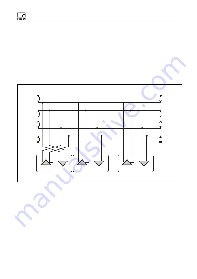
Connection of several load cells to a PC via RS-485
Line termination
Line termination
TB
TA
RB
RA
PC = Master
FIT5A_1 = Slave 01
FIT5A_89 = Slave 89
...
500
Ω
500
Ω
500
Ω
500
Ω
500
Ω
500
Ω
500
Ω
500
Ω
+5 V
+5 V
+5 V
+5 V
TxD on/off RxD
TB
TA
T
R
RB
RA
TxD on/off RxD
TB
TA
T
R
RB
RA
TxD on/off RxD
TB
TA
T
R
RB
RA
Fig. 6.1
Bus connection via RS‐485
Up to 89 load cells can be connected via the RS‐485 interface to a common
bus line, the total length of which can be as much as 1000 m. Bus cabling for
4wiremode is shown in Fig. 6.1.
Remember that many PCs do not have an RS‐485 interface. In this case, you
need an interface converter, such as the HBM converter (see Section 6.2).


