background image

21

2 1 0 0   B A L E B U S T E R

O P E R A T I N G   I N S T R U C T I O N S

WARNING: 

Improper hitch adjustment may cause separation of P.T.O., driveline when loading bale

or operating over uneven terrain. Separation may also occur if three point links are lifted excessively
high.

3.2.3 Starting the machine

With Tractor hooked up to the 2100 BALEBUSTER, try all functions on the machine.

1.

To unfold rack and deflector, loader tine frame:

a.     Place the tine frame pin in the unlocked position.

b.    When unfolding, keep bystanders away from the work area.

c.    Start the engine; tilt hinge frame hydraulically to allow the loader tine frame to be unfolded and lay
       on ground.

d.     Lock tine frame pin into working position.

e.     Tilt hinge frame hydraulically to working position.

f.     Unlock rack strap. Fold out rack and deflector. Lock into working position.

2.

Adjust the deflector.

With the engine at idle:

1.

Raise and lower the loading tines.

2.

Engage the bale conveyor, and adjust conveyor speed control valve on the 2100 BALEBUSTER.

3.

Engage the tractor PTO, and the rotor should start turning.  Listen for any odd noises and vibrations.

WARNING:

  After making all necessary hook-ups to tractor, be sure rotor chamber is clear of any

solid objects.  Make sure any bystanders are away from discharge before engaging PTO.  Flying
objects can cause serious injury or even death.  Stay clear of discharge side of machine unless
operator has stopped tractor engine and machine has stopped rotating.  Failure to follow these
instructions may result in severe injury.

To start the machine, perform the following steps:

1.

Adjust the deflector to desired position.

2.

Load bale into the 2100 BALEBUSTER. (See Section 3.2.6 for a description of this procedure.)

3.

Position the 2100 BALEBUSTER where you want to begin shredding the bale.

4.

Engage the PTO, and increase tractor engine speed so PTO is at 1000 RPM.

5.

Engage the bale conveyor, and check to see if the bale is turning in the right direction.  The proper
direction of bale rotation is indicated by the bale rotation decal located on the front of the 2100
BALEBUSTER.

Summary of Contents for 2100 BALEBUSTER

Page 1: ...Instructions and Parts Reference PO BOX 1940 JAMESTOWN ND 58402 1940 MAY 2012 0500115 2100 2100 2100 2100 2100 B B B B BALEB ALEB ALEB ALEB ALEBUSTER USTER USTER USTER USTER SERIAL NUMBER 2ICJ010100...

Page 2: ...A Tradition of Innovation Since 1966...

Page 3: ...eserves the right to make updates to the machine from time to time Even in the event of such updates you should still find this manual to be appropriate for the safe operation and maintenance of your...

Page 4: ...A Tradition of Innovation Since 1966...

Page 5: ...BALEBUSTER is designed to load and shred most types of baled livestock forage It is designed specifically for use on 6 1 2 ft diameter round bales weighing up to 1 500 pounds and 5 1 2 feet in length...

Page 6: ...As with all machinery care needs to be taken in order to insure the safety of the operator and those in the surrounding area The OPERATOR IS RESPONSIBLE for the safety of the operator and those in th...

Page 7: ...ation check 13 2 4 2100 BALEBUSTER shipping list 14 Section 3 Machine Operation 15 3 1 Introduction to the machine 15 3 1 2 Operator s station controls 15 3 1 3 Bale conveyor speed 16 3 1 4 Deflector...

Page 8: ...N 21 HJ 89000 38 MAIN FRAME ASSEMBLY S N 21 IJ 89100 AND UP 40 SHREDDER FRONT ASSEMBLY 42 PRESSURE RELIEF VALVE 44 REAR BEARING AND BALE GUIDE ASSEMBLY 46 ROTOR ASSEMBLY 48 BALE CONVEYOR ASSEMBLY THRU...

Page 9: ...L E B U S T E R O P E R A T I N G I N S T R U C T I O N S Part 1 Operating Instructions 2100 2100 2100 2100 2100 B B B B BALEB ALEB ALEB ALEB ALEBUSTER USTER USTER USTER USTER SERIAL NUMBER 2IC010100...

Page 10: ...intenance requirements and routine adjustments for the most efficient operation of your 2100 BALEBUSTER There is also a trouble shooting section that may help in case of problems in the field Any info...

Page 11: ...illustrated in Part 2 Parts Reference Complete and return the Warranty Registration Card Receipt of this form is required to activate the warranty Appendix A provides details of the warranty Operator...

Page 12: ...E IS NOT TO BE USED FOR ANY PURPOSE OTHER THAN THOSE EXPLAINED IN THE OPERATOR S MANUAL ADVERTISING LITERATURE OR OTHER DURATECH INDUSTRIES WRITTEN MATERIAL PERTAINING TO THE 2100 BALEBUSTER 1 1 Safet...

Page 13: ...t avoided may result in minor or moderate injury It may also be used to alert against unsafe practices Saf Saf Saf Saf Safety Aler ety Aler ety Aler ety Aler ety Alert Symbol t Symbol t Symbol t Symbo...

Page 14: ...Clothing Clothing must be sturdy and snug fitting but allow complete freedom of movement Avoid loosefitting jackets scarfs neckties jewelry flared or cuffed pants unconfined long hair or anything that...

Page 15: ...E TO FOLLOW THESE INSTRUCTIONS MAY RESULT IN SEVERE PERSONAL INJURY OR DEATH DANGER ROTATING FLAILS CAN KILL OR DISMEMBER KEEP CLEAR OF MACHINE UNTIL POWER TAKE OFF HAS BEEN DISENGAGED TRACTOR ENGINE...

Page 16: ...ields in place while machine is in operation 5 Keep hands feet hair and clothing away from moving parts 6 Keep others away from machine while in operation 7 Install safety locks before transporting or...

Page 17: ...4 Make sure the machine is in good operating condition and that all protective shields are in place and in proper working order Replace damaged shields before operating 5 Be sure all bystanders and o...

Page 18: ...place missing or damaged flails 3 Power takeoff shafts must be locked in place with protective PTO shields in place 4 Keep hands feet and clothing away from power driven parts 5 Never leave tractor co...

Page 19: ...re in good condition before applying pressure to the system 1 7 Towing road transport This machine is designed to fold for ease of transportation and storage 1 To fold rack and deflector loader and ti...

Page 20: ...he tractor used see section 3 2 2 for more information 2 Attach hitch brace 8100137 using the 5 8x2 bolts as shown in the drawing 3 Attach link pins 4800086 to hitch If installing a quick tach refer t...

Page 21: ...phases of operation 2 3 Machine operation check With Tractor hooked up to the 2100 BALEBUSTER try all functions on the machine When unfolding keep bystanders away from work area 1 Unfold rack and def...

Page 22: ...d 6 5000025 2 1 1 8 Lock Washer 7 4900024 2 1 1 8 Hex Nut Fine Thread 8 4800140 2 1 x3 Bolt 9 5000053 2 1 Lock Washer 10 4900031 2 1 Nut 11 4800115 2 3 4 x 2 1 2 Bolt 12 5000012 2 3 4 Lock Washer 13 5...

Page 23: ...for more information The PTO shaft which runs the rotor The bale conveyor chain Another tractor hydraulic circuit is used to control the bale conveyor s speed and direction If the tractor is equipped...

Page 24: ...r can be positioned for creating a windrow spreading bunkfeeding or stockpiling Lower the deflector for a narrower windrow and raise the deflector for a wider spread To change the position squeeze the...

Page 25: ...ded See section 3 4 2 for more information about adding or removing stripper plates In applications where a very coarse cut is desired the stripper plate may be removed 3 1 6 Rotor The rotor flails sh...

Page 26: ...er job of chopping forage and also minimizes twine buildup on the rotor Twine buildup should be kept to a minimum to reduce fire hazard WARNING SERIOUS INJURY COULD RESULT IF MACHINE IS ALLOWED TO TIP...

Page 27: ...ils and attachment bolts Rotor for twine build up Chains for proper tension and condition Check for loose bolts worn or broken parts All lubrication points have been serviced Lug nuts for tightness Co...

Page 28: ...on the main frame so that the 34 to 36 inch measurement will be obtained when the tractor is attached 5 Reattach the tractor to the 2100 BALEBUSTER 6 Attach the PTO shaft to the tractor PTO shaft Dep...

Page 29: ...onveyor and adjust conveyor speed control valve on the 2100 BALEBUSTER 3 Engage the tractor PTO and the rotor should start turning Listen for any odd noises and vibrations WARNING After making all nec...

Page 30: ...off for chain conveyor 2 Disengage PTO 3 Lower machine to ground level 4 Place transmission in park or set park brake 5 Shut Off engine and remove key 6 Wait for all movement to stop 3 2 5 Unhitching...

Page 31: ...2100 BALEBUSTER To load bales into the 2100 BALEBUSTER perform the following steps NOTE The loading area should be flat and level 1 Position the 2100 BALEBUSTER ahead and to the side of the bale Exte...

Page 32: ...e signs safety chain and other possible requirements NOTE A bracket is located on the front of the 2100 BALEBUSTER to hold the front half of the PTO shaft 3 3 1 Preparing for storage WARNING When prep...

Page 33: ...storage When ordering parts always specify machine serial number and the part number of the replacement part Part numbers can be found in the parts section of this manual 3 3 2 Removing from storage...

Page 34: ...control 3 4 2 Changing length of cut CHANGING STRIPPER PLATES Adding stripper plates will produce a finer cut and removing plates will produce a coarser cut See Figure 3 7 and section 3 1 5 For a fin...

Page 35: ...Moving the lever clockwise will speed up the conveyor and make a coarser product For tractors with PFC type hydraulic systems This valve should be set in the full open position Conveyor speed can be c...

Page 36: ...es 40 psi 7 Discharge deflector has adjusting straps to allow forage to be spread to any desired width See section 3 4 Adjusting the machine for more information 8 Bale deflector has been preset at fa...

Page 37: ...O universal joints and telescoping shaft 3 lubrication points see Figure 4 2 3 Main frame pivot bushings 2 lubrication points see Figure 4 3 4 Swivel wheel pivot 2 lubrication points see Figure 4 4 CA...

Page 38: ...pivot lubrication point one of two 4 3 Axle wheels tires Repack wheel bearings annually 4 4 General appearance Clean all mud dirt grease and other foreign material from the exterior of the machine Cut...

Page 39: ...t s i p y b g n i k a e l l i o c i l u a r d y H 2 r e d n i l y c n i c i l u a r d y h e c a l p e r r o r i a p e R 2 r e d n i l y c e s r a o C o o T e g a r o F 5 t s a f o o t d e e p s r o y...

Page 40: ...32 2 1 0 0 B A L E B U S T E R O P E R A T I N G I N S T R U C T I O N S A Tradition of Innovation Since 1966...

Page 41: ...ich originally sold the product and all warranty adjustments must be made through same This warranty does not apply to tires or bearings or any other trade accessories not manufactured by DuraTech Ind...

Page 42: ...W W W Wor or or or orking P king P king P king P king Position osition osition osition osition Length 153 Width 156 1 2 Height 116 3 4 T T T T Tr r r r ranspor anspor anspor anspor ansport P t P t P...

Page 43: ...s 3 Hydraulic system 8 gallons per minute 30 liters per minute minimum 1 800 Psi minimum 105 bar two way valves 4 Two double acting control valves 5 The tractor must be of equal or greater weight than...

Page 44: ...36 2 1 0 0 B A L E B U S T E R O P E R A T I N G I N S T R U C T I O N S A Tradition of Innovation Since 1966...

Page 45: ...00 2100 2100 2100 2100 B B B B BALEB ALEB ALEB ALEB ALEBUSTER USTER USTER USTER USTER SERIAL NUMBER 2ICJ010100 AND UP TM Part 2 Parts Reference 37 2 1 0 0 B A L E B U S T E R P A R T S R E F E R E N C...

Page 46: ...38 2 1 0 0 B A L E B U S T E R P A R T S R E F E R E N C E M A I N F R A M E A S S E M B L Y T H R U S N 2 1 H J 8 9 0 0 0...

Page 47: ...1 2 8 4800044 2 PIN COT 5 32X1 1 2 9 4800106 2 BOLT HEX 5 8X1 1 2 10 4800114 8 BOLT HEX 1 2X2 11 4800911 2 PIN LYNCH 1 4X2 1 2 12 4900001 8 NUT HEX 1 2 NC 13 4900023 1 NUT TPLCK 3 8 NC 14 4900054 2 N...

Page 48: ...40 2 1 0 0 B A L E B U S T E R P A R T S R E F E R E N C E M A I N F R A M E A S S E M B L Y S N 2 1 I J 8 9 1 0 0 A N D U P...

Page 49: ...114 8 BOLT HEX 1 2X2 10 4800911 2 PIN LYNCH 1 4X2 1 2 11 4900001 8 NUT HEX 1 2 NC 12 4900005 6 NUT HEX 5 8 NC 13 4900023 1 NUT TPLCK 3 8 NC 14 4900054 2 NUT CASTLE 1 2 NF 15 5000003 2 WASH LOCK 5 8 16...

Page 50: ...42 2 1 0 0 B A L E B U S T E R P A R T S R E F E R E N C E S H R E D D E R F R O N T A S S E M B L Y...

Page 51: ...29 4900009 4 NUT HEX 1 4 NC 30 4900014 2 NUT TPLCK 1 2 NC 31 4900023 2 NUT TPLCK 3 8 NC 32 4900139 1 NUT TPLCK 3 4 GR8 NC 33 4900179 30 NUT TPLCK RTR 5 8 NF GR9 34 5000001 29 WASH FLAT 3 8 35 5000002...

Page 52: ...44 2 1 0 0 B A L E B U S T E R P A R T S R E F E R E N C E P R E S S U R E R E L I E F V A L V E...

Page 53: ...9 4900009 4 NUT HEX 1 4 NC 30 4900014 2 NUT TPLCK 1 2 NC 31 4900023 2 NUT TPLCK 3 8 NC 32 4900139 1 NUT TPLCK 3 4 GR8 NC 33 4900179 30 NUT TPLCK RTR 5 8 NF GR9 34 5000001 29 WASH FLAT 3 8 35 5000002 5...

Page 54: ...46 2 1 0 0 B A L E B U S T E R P A R T S R E F E R E N C E R E A R B E A R I N G A N D B A L E G U I D E A S S E M B L Y...

Page 55: ...HEX 5 8 NC 29 4900009 4 NUT HEX 1 4 NC 30 4900014 2 NUT TPLCK 1 2 NC 31 4900023 2 NUT TPLCK 3 8 NC 32 4900139 1 NUT TPLCK 3 4 GR8 NC 33 4900179 30 NUT TPLCK RTR 5 8 NF GR9 34 5000001 29 WASH FLAT 3 8...

Page 56: ...48 2 1 0 0 B A L E B U S T E R P A R T S R E F E R E N C E R O T O R A S S E M B L Y...

Page 57: ...009 4 NUT HEX 1 4 NC 30 4900014 2 NUT TPLCK 1 2 NC 31 4900023 2 NUT TPLCK 3 8 NC 32 4900139 1 NUT TPLCK 3 4 GR8 NC 33 4900179 30 NUT TPLCK RTR 5 8 NF GR9 34 5000001 29 WASH FLAT 3 8 35 5000002 50 WASH...

Page 58: ...50 2 1 0 0 B A L E B U S T E R P A R T S R E F E R E N C E B A L E C O N V E Y O R A S S E M B L Y T H R U S N 2 1 H J 8 9 0 0 0...

Page 59: ...CR SET SQ 3 8X1 1 4 NC 13 4800393 48 BOLT HEX 5 16X7 8 GR8 14 4900001 4 NUT HEX 1 2 NC 15 4900002 4 NUT HEX 3 8 NC 16 4900003 4 NUT HEX 5 16 NC 17 4900026 1 NUT JAM 3 8 NC 18 4900027 4 NUT FLG TPLCK 5...

Page 60: ...52 2 1 0 0 B A L E B U S T E R P A R T S R E F E R E N C E B A L E C O N V E Y O R A S S E M B L Y S N 2 1 I J 8 9 1 0 0 A N D U P...

Page 61: ...Q 3 8X1 1 4 NC 14 4800393 48 BOLT HEX 5 16X7 8 GR8 15 4900001 4 NUT HEX 1 2 NC 16 4900002 4 NUT HEX 3 8 NC 17 4900003 4 NUT HEX 5 16 NC 18 4900026 1 NUT JAM 3 8 NC 19 4900027 4 NUT FLG TPLCK 5 16 NC 2...

Page 62: ...54 2 1 0 0 B A L E B U S T E R P A R T S R E F E R E N C E B A L E L O A D E R A S S E M B L Y...

Page 63: ...ON B A L E L O A D E R A S S E M B L Y 1 4800103 1 PIN COT 1 4X2 2 4800248 2 BOLT HEX 3 4X6 3 4900139 2 NUT TPLCK 3 4 GR8 NC 4 5000018 1 WASH BUSH 1 10GA 5 8100043 2 TINE 6 8100044 1 PIN HINGE FRAME T...

Page 64: ...56 2 1 0 0 B A L E B U S T E R P A R T S R E F E R E N C E R A C K D E F L E C T O R A S S E M B L Y...

Page 65: ...OCK 1 2 10 5000019 12 WASH LOCK 3 8 11 6100031 2 SPRING COMP 072W 25 32OD 12 6100075 1 BRKT TORSION DFLCRT 13 8100791 1 BELT DFLCTR 6 x 73 3 4 13 8100819 opt BELT DFLCTR 18 x 73 3 4 14 8101046 1 DFLCT...

Page 66: ...58 2 1 0 0 B A L E B U S T E R P A R T S R E F E R E N C E S H I P P I N G K I T H A R D W A R E...

Page 67: ...OLT HEX 1X3 NC 5 4900004 2 NUT HEX 3 4 NC 6 4900005 4 NUT HEX 5 8 NC 7 4900024 2 NUT HEX 1 1 8 12 NF 8 4900031 2 NUT HEX 1 NC 9 5000002 4 WASH FLAT 5 8 10 5000003 4 WASH LOCK 5 8 11 5000005 2 WASH FLA...

Page 68: ...B A L E B U S T E R P A R T S R E F E R E N C E H Y D R A U L I C A S S E M B L Y 4 6 10 7 11 7 3 3 6 1C 2 6 1A 9 1A 1C 1B 1D 5 5 12 12 2 3 4 hoses total 8 4 total 1B 1D machine front machine rear re...

Page 69: ...w 6 3800483 3 3 4 MOR x 3 4 MJIC x 3 4 MJIC Run Tee 7 3800477 2 3 4 MOR x 3 4 MJIC 8 3800694 4 3 4 FOR Quick CPLR 9 4000234 1 RLF VALVE 4000417 1 VALVE HYD RELF 1000 PSI 4000418 1 VALVE HYD RELF 1800...

Page 70: ...62 2 1 0 0 B A L E B U S T E R P A R T S R E F E R E N C E F L O W C O N T R O L V A L V E 4 0 0 0 2 1 3...

Page 71: ...A R T S R E F E R E N C E ITEM PART NO QTY DESCRIPTION F L O W C O N T R O L V A L V E 4 0 0 0 2 1 3 1 4000213 1 Flow Control Valve o ring thread 2 4000031 1 Handle Assembly 3 4 4000091 1 Seal Kit Fl...

Page 72: ...64 2 1 0 0 B A L E B U S T E R P A R T S R E F E R E N C E F L O W C O N T R O L V A L V E 4 0 0 0 3 3 1...

Page 73: ...T S R E F E R E N C E F L O W C O N T R O L V A L V E 4 0 0 0 3 3 1 ITEM PART NO DESCRIPTION 4000331 VALVE FLW CRTL 8FOR 3 8 4000334 HDL ASSY V HYD 5 10 11 13 4000335 SEAL KIT V HYD INCLUDES 2 EACH OF...

Page 74: ...66 2 1 0 0 B A L E B U S T E R P A R T S R E F E R E N C E O R B I T M O T O R...

Page 75: ...A L E B U S T E R P A R T S R E F E R E N C E ITEM PART NO QTY DESCRIPTION O R B I T M O T O R 1 3900025 MTR HYD 17 9 0 RING 2 3900002 1 MTG FLG 3 6200011 1 KEY WDF 1 4X1 15 808 4 7501038 1 UNI SEAL...

Page 76: ...68 2 1 0 0 B A L E B U S T E R P A R T S R E F E R E N C E W H E E L A N D B E A R I N G...

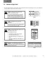
Page 77: ...olt 14 x 8 3 2600013 2 Tire 9 5L x 14 8 ply 2 3 2600825 2 Whl Imp 9 5 x 14 Tire Rim 4 2900013 1 Cap 5 4800157 1 Pin Cot 3 16 x 2 6 4900054 1 Nut Spindle 7 5000055 1 Washer 7 8 Flat 8 2900018 1 Cone Ou...

Page 78: ...70 2 1 0 0 B A L E B U S T E R P A R T S R E F E R E N C E P T O A S S E M B L Y 3 6 0 0 1 0 7 S T E E L G U A R D...

Page 79: ...3 3600079 1 Yoke 1 3 4 Rd 4 3600042 2 Repair Kit 5 3600109 1 Yoke and Tube 6 3600283 N A Bearing Retainer 7 3600283 N A Nylon Bearing 8 3600110 1 Male Guard Tube Inner Steel Guard 9 3600283 1 Nylon C...

Page 80: ...72 2 1 0 0 B A L E B U S T E R P A R T S R E F E R E N C E P T O A S S E M B L Y 3 6 0 0 5 1 6 P L A S T I C G U A R D...

Page 81: ...TO 242 22554 35R PLASTIC GUARD 1 3600042 2 CROSS BEARING KIT 35 2 3600084 1 YOKE 35W 1 3 8 21 SPL QD 3 3600112 1 35W YOKE SHAFT 4 3600109 1 35W YOKE TUBE 5 3600079 1 YOKE 35W 1 3 4 RD CLAMP 6 7 360051...

Page 82: ...74 2 1 0 0 B A L E B U S T E R P A R T S R E F E R E N C E B A L E B U S T E R Q U I C K T A T C H...

Page 83: ...C H 1 8100652 1 Quick Hitch Mount Left shown 2 8100653 1 Quick Hitch Mount Right 3 8100131 2 Reversible Adapter Bushing 4 4800189 2 1 1 8 x 9 Grade 5 Hex Bolt 5 5000025 2 1 1 8 Lock Washer 6 4900037 2...

Page 84: ...76 2 1 0 0 B A L E B U S T E R P A R T S R E F E R E N C E T A I L L I G H T S A N D O P E R A T O R S M A N U A L E N C L O S U R E...

Page 85: ...T NO QTY DESCRIPTION T A I L L I G H T S A N D O P E R A T O R S M A N U A L E N C L O S U R E 1 4800277 8 BOLT HEX 1 4X1 2 4800503 4 BOLT HEX 1 4X5 8 NC 3 4900009 16 NUT HEX 1 4 NC 4 5000024 16 WASH...

Page 86: ...B U S T E R P A R T S R E F E R E N C E 2 1 0 0 B A L E B U S T E R D E C A L R E Q U I R E M E N T S 1 6500020 3 6500034 4 6500035 5 6500036 8 6500040 9 6500041 6 6500037 7 6500085 10 6500043 11 6500...

Page 87: ...TION 6 6500037 1 ATTENTION ADJUST HITCHES 7 6500085 1 DANGER ROTATING DRIVE LINE 8 6500040 2 WARNING KEEP AII SHIELDS IN PLACE 9 6500041 1 WARNING FOR YOUR PROTECTION 10 6500043 2 WARNING NO RIDERS 11...

Page 88: ...80 2 1 0 0 B A L E B U S T E R P A R T S R E F E R E N C E 2 1 0 0 B A L E B U S T E R D E C A L L O C A T I O N S 3 10 4 8 1 2 2 1 3 4 11 8 5 11 9 6...

Page 89: ..._________________________________________________ __________________________________________________________________ __________________________________________________________________ ________________...

Page 90: ...82 2 1 0 0 B A L E B U S T E R P A R T S R E F E R E N C E A Tradition of Innovation Since 1966...

Reviews: