background image

10

230 V AC 

L1

N

3 2 1

4

3 2 1

4

L1

N

Uout
Uout +24 V DC

Bus

GND

1

2
3
4

1 2 3 4 5 6 7

BU

S

GN

D

24 

V

24 

V

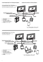
WLAN-Box

WLAN box

230 V AC 

Notstrom

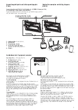
RWA-Kompaktzentrale RAZ K

SHEV compact central unit RAZ K

RWA-Kompaktzentrale RAZ K

SHEV compact central unit RAZ K

+24 V DC

Emergency current

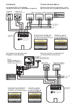
Terminal connection diagram (cont‘d)

Anschlussplan (Forts.)

Anschlussplan für RWA-Kompaktzentrale RAZ K 

Terminal connection diagram for   

SHEV compact central unit RAZ K

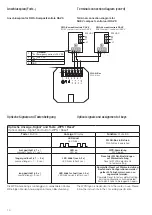
Optical signals and  assignment of keys

Optische Signale und  Tastenbelegung

Optische Anzeige „Signal“ und Taste „WPS / Reset“ 

Optical display „Signal“ and button „WPS / Reset“

Taste / 

Button

Anzeige / 

Display

Funktion / 

Function

-

LED blinkt

LED blinks

WLAN-Box in Betrieb

WLAN-Box in operation

kurz gedrückt (< 1 s) 

pressed shortly (< 1 sec.)

LED an 

LED on

WPS-Anmeldung 

WPS logon

länger gedrückt (> 1 ... 5 s) 

pressed longer (> 1 ... 5 sec.)

LED blinkt (nach 2 s) 

LED blinks (after 2 sec.)

Reset der WLAN-Einstellungen 

auf Werkseinstellung

Reset of WLAN adjustments 

to  factory setting

lang gedrückt (> 5 s) 

pressed long (> 5 sec.)

LED blinkt schnell (nach 5 s) 

LED blinks quickly (after 5 sec.)

Kompletter Reset auf Werkseinstellung. 

Bestehende Konfigurationen werden 

gelöscht. Teilnehmer müssen neu 

 angemeldet  werden.

Complete Reset to factory default setting. 

Existing configurations will be deleted. 

Participants have to be logged on again.

Die WPS-Anmeldung ist abhängig vom verwendeten Router. 
Bitte folgen Sie den Anweisungen in dessen Beschreibung.

The WPS logon is dependant from the router in use. Please 
follow the instructions in the concerning specification.

Summary of Contents for WLAN-Box

Page 1: ...ol benötigt Product description The WLAN Box is to be used for wireless control of products with a HAUTAU bus interface via WLAN radio signal The control will be effected by means of mobile terminals via a direct connection to the WLAN Box or via on site WLAN routers For control and configuration of the products the optional available HAUTAU ConfigTool is required Inhaltsverzeichnis Seite Wichtige...

Page 2: ...he safe operation Mortal danger due to electricity The WLAN Box is suitable for control of 230 V products with a HAUTAU bus interface Mortal danger by touching cables that are live During service maintenance at the unit the supply voltage has to be dis connected via isolating link at all poles Protect the system against unintentional re starting The isolating link has to be labeled clearly Danger ...

Page 3: ...der Montage der Antriebe beachten Sie bitte die auftretenden Kräfte Überprüfen Sie zum Abschluss alle Funktionen Funktions und Betriebsanzeigen sowie den Schwenkbereich der Antriebe Füllen Sie die Errichter bescheinigung im Kontrollbuch aus und leiten Sie das Anforderungsformular sowie den dazugehörigen Brief umschlag an den Betreiber weiter Zeichnungen Montage und Betriebsanleitung sind für einen...

Page 4: ...line siehe Leitungslängen und Querschnitte refer to Wire lengths and cross sections 3 x 0 8 mm Zuleitung 230 V AC 50 Hz Feeder wire 230 V AC 50 Hz 4 5 1 1 2 3 Zuleitung 230 V AC Feeder wire 230 V AC Betriebsspannung 24 V DC Operating voltage 24 V DC siehe Leitungslängen und Querschnitte refer to Wire lengths and cross sections Antriebs und Busleitung Drive line and bus line 2 x 3 x 0 8 mm 3 x 0 8 ...

Page 5: ...t wird an alle konfigurierten Geräte der ZU Befehl gesendet Totmann Betrieb übergeordneter Befehl Solange der Eingang geschaltet bleibt werden die Befehle AUF STOP ZU blockiert Totmann Betrieb vom Taster und WLAN Eingang Hier kann beispielsweise ein Regenmelder angeschlossen werden Anschluss für Connection for 1 Verriegelung Locking 2 Lüftungstaster ZU Ventilation pushbutton CLOSE 3 Lüftungstaster...

Page 6: ...ths from the energy source until the last junction box are to be observed acc to the used cable cross sections and the maximum current consumption per drive group ATTENTION The VDE regulations or equivalent are to be observed optional Lüftungstaster LT Ventilation pushbutton LT Installation of the WLAN Box The WLAN Box is designed for installation in an on site flush housing The place of installat...

Page 7: ...connection for 24 V DC drives version SKA 20 comfort drive and PRIMAT S kompakt 195 Anschlussplan in Kombination eines Windgebers und Regenmelders Terminal connection in combination with a wind trans mitter and rain sensor 24 V phase controlled change version 24 V bus controlled 230 V phase controlled Exit 24 V phasengesteuert Version ändern 24 V busgesteuert 230 V phasengesteuert Beenden für die ...

Page 8: ...MAT E kompakt 195 versorgt Maximal kann eine WLAN Box aus dem Netzteil vom PRIMAT E kompakt 195 versorgt werden Terminal connection diagram for 230 V AC drive version PRIMAT E kompakt 195 The WLAN Box will be supplied from the mains adapter of the drive PRIMAT E kompakt 195 directly At most one WLAN Box can be supplied out of the mains adapter of the PRIMAT E kompakt 195 für die Antriebe ist per C...

Page 9: ...sed for the power supply of the WLAN box Datenkabel Data cable Bus Uout 24 V DC GND braun brown rot red schwarz black 1 2 3 4 5 6 7 BUS GND 24 V 24 V HAUTAU Bus GND 24 V dezentraler Lüfter VENTRA 301 E N decentralised window fan Bus Uout 24 V DC GND braun brown rot red schwarz black Terminal connection diagram cont d Anschlussplan Forts Anschlussplan für mehrere 230 V AC Antriebe Typ PRIMAT E komp...

Page 10: ...blinks WLAN Box in Betrieb WLAN Box in operation kurz gedrückt 1 s pressed shortly 1 sec LED an LED on WPS Anmeldung WPS logon länger gedrückt 1 5 s pressed longer 1 5 sec LED blinkt nach 2 s LED blinks after 2 sec Reset der WLAN Einstellungen auf Werkseinstellung Reset of WLAN adjustments to factory setting lang gedrückt 5 s pressed long 5 sec LED blinkt schnell nach 5 s LED blinks quickly after ...

Page 11: ...U Busses to connect the HAUTAU bus 6 Eingang 24 V DC Input 24 V DC Betriebsspannung WLAN Box operational voltage WLAN Box 7 GND GND GND für die Betriebsspannung GND for the operational voltage Die Funktionen sind abhängig von der Version der WLAN Box Firmware der Art der verwendeten Produkte mit HAUTAU Schnittstelle und der Version vom HAUTAU ConfigTool Um den Betrieb zu gewährleisten wird die Sof...

Page 12: ...es Zubehör HAUTAU Software Applikation App ConfigTool Zur Parametrierung der WLAN Box und Bedienung Technical data Operating supply Supply voltage 24 V DC 10 30 Ripple 20 related to nominal voltage Power consumption in broadcast mode approx 1 5 W Power consumption in standby mode approx 1 W Current consumption in broadcast mode approx 60 mA Current consumption in standby mode approx 40 mA Output v...

Reviews: