background image

5

A2

B

C

C

B

A1

A1

P1

A2

P1

A2

P1

B

C

A2

P1

B

C

3

3

**

1

*

2

2

3

3

**

1

*

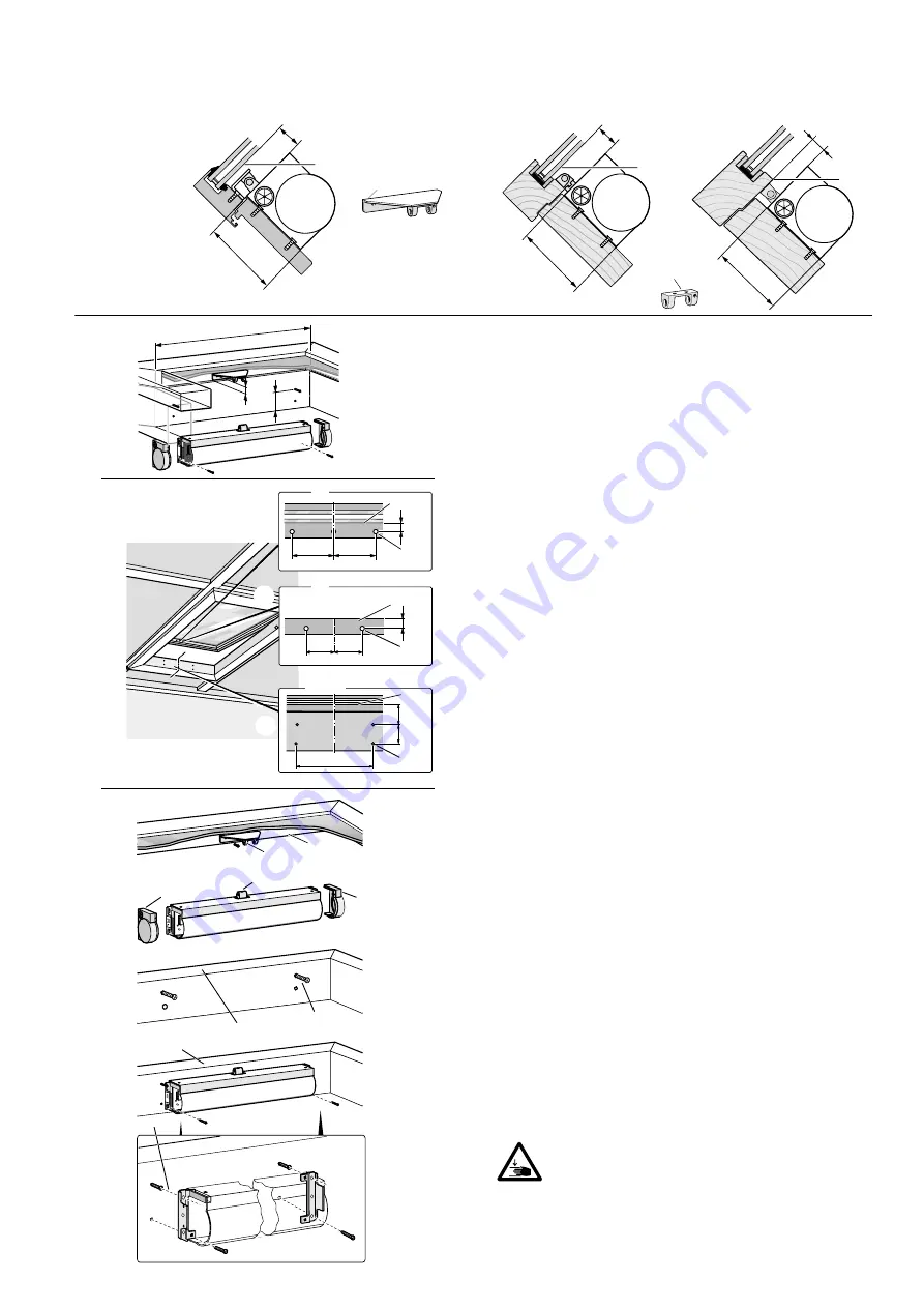
Varianten 

Options

A1   Montage mit Flügelplatte


mounting with coupling plate

A2   Montage mit Flügelbock


mounting with hinge bracket

Montage am Dachfenster

Mounting on skylight

5

4

6

7

6

8

9

9

8

A

B

C

1

1

2

3

4

5

6

7

37,5

37,5

Ø 3,6

17

P1

9

9

P1

17

38

50

P1

X

A1

A2

A1/A2

Ø 3,6

Ø 3,6

Mindestabstände beachten


Check minimum spacings

P1

 = 

Bezugspunkt! / 

Reference Point!

A

  =   600 mm

B

  =     75 mm   

Auflagefläche des Antriebs


supporting surface drive

C

  =    25 mm    

Freiraum für Flügelbock


clearance for hinge bracket

Anreißen 

Positioning

1

  Mitte des Fensterflügels markieren, Löcher für 

Flügelplatte A1 und Flügelbock A2 anreißen und 

bohren. Mindestmaße beachten!

1

  Mark the centre of the casement, mark and drill the 

holes for the coupling plate 

A1

 and hinge bracket 

A2

.  

Note minimum dimensions requirements!

2


Mitte des Rahmens markieren, Löcher für Antrieb 

anreißen und bohren.

2

 Mark centre of frame, mark and drill holes for drive.

  =  515 mm

Anschrauben  

Attaching

3


Flügelbock/-platte 4 an Fensterflügel 5  

anschrauben.

3

 Screw hinge bracket/coupling plate 

4

 on casement 

5

.

4


Endkappen 6 vom Antrieb entfernen und Ketten-

kuppler 7 anschrauben.

4

  Remove end caps 

6

 from drive and screw on chain end 

coupling 

7

.

5

 + 

6


Obere Schrauben 9 für den Antrieb einige 

Umdrehungen in Fensterrahmen 8  

einschrauben.

5

 + 

6

  To attach the drive, first screw the upper  

screws 

a few turns into the window frame 

8

.

7


Antrieb an oberen Schrauben 9 einhängen und alle 

vier Schrauben festziehen.

7

  Suspend drive by upper screws 

9

, insert the two  

remaining screws and then tighten all four screws.

Vorsicht: Verletzungsgefahr durch herunter- 

schlagendes Fenster!
Caution: 

Risk of injury if the window falls down!

Summary of Contents for EKA 45-400

Page 1: ...hout the publisher s approval In consideration of progress we reserve the right to apply construction modifications and to consequently change any figures dimensions wire specifications etc The figures do not show items in their actual size and are also not of the same proportion B L H 70 8 56 5 18 A Dachfenster DF Skylight DF B Kippfenster KF Bottom hung open in window KF Vorsicht Verletzungsgefa...

Page 2: ...rive has been constructed and tested in conformity with all applicable European directives A corresponding declaration of incorporation is available You may not operate the equip ment unless a declaration of conformity is available for the overall system The drive complies with the state of the art and requires quali fied personnel for installation maintenance etc Personnel The professional instal...

Page 3: ...d no guarantee nor service is granted if products made by outside manufacturers are used Reliable operation without any damage and hazards requires that installation setup be made carefully in accordance with these instructions If spare parts or extension components are required or desired use only original spare parts Applications on tilt windows require the installation of scissor type safety ca...

Page 4: ...ective class Class III acc to DIN EN 61140 VDE 0140 1 Range of temperatures approx 10 C to 50 C Hook out machanics double chain according to the zipper principle Housing material aluminium profile Colour silver grey RAL 9006 powdercoated Special colours white RAL 9016 and on request to RAL colour card End caps plastic black Dimensions W x H x L 70 x 56 5 x 541 mm Min sash heigth 800 mm with tilt c...

Page 5: ...or the coupling plate A1 and hinge bracket A2 Note minimum dimensions requirements 2 Mitte des Rahmens markieren Löcher für Antrieb anreißen und bohren 2 Mark centre of frame mark and drill holes for drive X 515 mm Anschrauben Attaching 3 Flügelbock platte 4 an Fensterflügel 5 anschrauben 3 Screw hinge bracket coupling plate 4 on casement 5 4 Endkappen 6 vom Antrieb entfernen und Ketten kuppler 7 ...

Page 6: ... Löcher 2 für Antrieb anreißen und bohren Abstand X kontrollieren 4 Mark the centre of the frame mark out and drill holes 2 for the drive Check distance X X 484 mm Anschrauben Attaching 5 Flügelbock 2 an Fensterrahmen 1 anschrauben 5 Screw hinge bracket 2 onto the window frame 1 6 7 Endkappen 3 vom Antrieb 4 entfernen und Kettenkuppler 5 anschrauben 6 7 Remove end caps 3 from drive 4 and screw on ...

Page 7: ...required in case of a 9 5 2 Kippkonsole tilt console 3 Zylinderschrauben M5 x 12 cylinder head screws M5 x 12 4 Mutter M5 nur bei a 19 5 nut M5 only in case of a 19 5 7 15 19 15 19 15 19 Flügel a 9 5 Sash 77 max 90 max 90 max 90 Blendrahmen Zwischenstück Spacer Frame 77 18 a 525 Blendrahmen Frame Blendrahmen Frame Flügel Sash Zwischenstück Spacer Flügel Sash 19 5 a 19 5 a 28 5 77 28 5 9 5 min 18 m...

Page 8: ... schliessen 1 Connect black cable 1 L open to open wall switch Connect brown cable 3 L close to close wall switch Connect blue cable 2 N to neutral conductor Ensure sufficient room to allow testing check functionality close switch junction box Dichtschluss einstellen Adjusting closing pressure 2 Fenster 5 schließen Kette ganz einfahren und Abstand X zwischen Kettenkuppler 4 und Flügel platte bock ...

Reviews: