60
4000392150
E02.16
USA / GB
HA32RTJ PRO - HA100RTJ PRO - HA41RTJ PRO - HA130RTJ PRO
C
- Maintenance
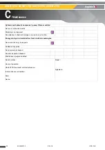
7.3.3.3 - Evaluation of leaks on hydraulic cylinders
These measures must be taken each time an anomaly has been detected in the hydraulic
cylinder during daily inspection and periodic maintenance checks.
Generic Control :
• Position a load equal to the rated capacity on the cage (or platform).
• Raise the cage (or the platform) using the ground control box. To activate the cylinder to be tested,
proceed as follows :
• Lift Arm hydraulic cylinder : Lift the arm to approximately half full height. The telescopic boom should
be fully extended and in the horizontal position. (For machines fitted with).
• Boom lifting cylinder or Jib cylinder : Lift the concerned equipment (boom or jib) of approximately half
way. Extend the telescope to its maximum.
• Telescoping cylinder : Lift the boom to its maximum angle and telescope approximately 50 cm.
• Measure the distance between the floor of the cage (or of the platform) and the ground.
• Leave the machine in this condition for 15 mn (minutes).
• Measure the distance between the floor of the cage (or of the platform) and the ground.
• If the difference between two measurements does not exceed 4 cm : the test validates correct
operation.
• If the difference between two measurements exceeds 4 cm, contact HAULOTTE Services® or carry
out the additional tests described below.
Control cylinder by cylinder :
• Position a load equal to the rated capacity on the cage (or platform).
• Perform the movement of the concern cylinder to half of its stroke.
• Fix the cylinder with a comparator :
• Attach the body of the comparator on the cylinder rod.
• The needle of the comparator must be in contact with the end of the casing of the cylinder.
• The target is to measure the creep of the cylinder rod.
• If the creep of the cylinder rod is higher than the values indicated in the table below, replace the
cylinder.
Type of cylinders
Maximum drift authorised due to an internal leak of
the cylinder
Lift cylinder arm or boom (Machine with working heights
> 26 m(85 ft4 in))
After 10 mn, creep
< 0,2 mm
After 60 mn, creep
< 1 mm
Outriggers cylinder, Oscillating axle locking, Lift cylinder arm
or boom (Machine with range-limiting system)
After 10 mn, creep
< 0,5 mm
After 60 mn, creep
< 2,5 mm
Lift cylinder arm or boom, Telescoping, Compensation, ...
After 10 mn, creep
< 1 mm
After 60 mn, creep
< 6 mm
Steering cylinder
After 10 mn, creep
< 1,5 mm
After 60 mn, creep
< 9 mm
Summary of Contents for HA100RTJ PRO
Page 2: ...2 4000392150 E02 16 USA GB HA32RTJ PRO HA100RTJ PRO HA41RTJ PRO HA130RTJ PRO...
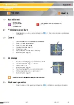
Page 64: ...64 4000392150 E02 16 USA GB Control Oil change Wheel reducer E002 15 mn Notes...
Page 66: ...66 4000392150 E02 16 USA GB Replacement Hydraulic filter cartridge E003 15 min Notes...
Page 68: ...68 4000392150 E02 16 USA GB Filling up Oil change Fuel tank E004 15 mn Notes...
Page 76: ...76 4000392150 E02 16 USA GB Replacement Tightening Wheel E006 15 min Notes...
Page 78: ...78 4000392150 E02 16 USA GB Tightening Screws bolts and nuts E007 15 min Notes...
Page 80: ...80 4000392150 E02 16 USA GB Control Oil change Turntable rotation gearbox E008 15 mn Notes...
Page 86: ...86 4000392150 E02 16 USA GB Control Lubrication Chains E016 Notes...
Page 94: ...94 4000392150 E02 16 USA GB Control Filling up Battery charge Battery E018 10 min Notes...
Page 96: ...96 4000392150 E02 16 USA GB Lubrication Telescope E022 15 mn Notes...
Page 140: ...2 Electrical diagram HA32RTJ PRO HA100RTJ PRO HA41RTJ PRO HA130RTJ PRO 1 2 ENGINE PART II...
Page 141: ...3 Electrical diagram HA32RTJ PRO HA100RTJ PRO HA41RTJ PRO HA130RTJ PRO 1 3 TURRET PART...
Page 142: ...4 Electrical diagram HA32RTJ PRO HA100RTJ PRO HA41RTJ PRO HA130RTJ PRO...
Page 143: ...5 Electrical diagram HA32RTJ PRO HA100RTJ PRO HA41RTJ PRO HA130RTJ PRO...
Page 144: ...6 Electrical diagram HA32RTJ PRO HA100RTJ PRO HA41RTJ PRO HA130RTJ PRO...
Page 145: ...7 Electrical diagram HA32RTJ PRO HA100RTJ PRO HA41RTJ PRO HA130RTJ PRO 1 4 CHASSIS PART...
Page 146: ...8 Electrical diagram HA32RTJ PRO HA100RTJ PRO HA41RTJ PRO HA130RTJ PRO 1 5 BASKET PART...
Page 147: ...9 Electrical diagram HA32RTJ PRO HA100RTJ PRO HA41RTJ PRO HA130RTJ PRO...
Page 149: ...11 Electrical diagram HA32RTJ PRO HA100RTJ PRO HA41RTJ PRO HA130RTJ PRO 1 7 NEW ARCHITECTURE...
Page 150: ...12 Electrical diagram HA32RTJ PRO HA100RTJ PRO HA41RTJ PRO HA130RTJ PRO 1 8 MINIDAT...
Page 152: ...2 Hydraullic diagram HA32RTJ PRO HA100RTJ PRO HA41RTJ PRO HA130RTJ PRO 1 2 FOLIO 2 3...
Page 153: ...3 Hydraullic diagram HA32RTJ PRO HA100RTJ PRO HA41RTJ PRO HA130RTJ PRO 1 3 FOLIO 3 3...
Page 155: ...5 Hydraullic diagram HA32RTJ PRO HA100RTJ PRO HA41RTJ PRO HA130RTJ PRO 2 2 FOLIO 2 3...
Page 156: ...6 Hydraullic diagram HA32RTJ PRO HA100RTJ PRO HA41RTJ PRO HA130RTJ PRO 2 3 FOLIO 3 3...


