background image

INSTALLATION

16

Form No. UGAM-0908

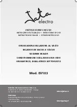
Figure 16. Hanger Post Mounting

Electrical Wiring Hook-Up

Refer to the ELECTRICAL RATING CHARTS for unit

specific information.

ELECTRIC SHOCK HAZARD: For hard-wired

units, all electrical connections must be in

accordance with local electrical codes and any

other applicable codes. Connections should be

made by a qualified, licensed electrician.

NOTE: If the unit being installed is not shown or

listed in this manual, refer to the wiring

diagram supplied with the unit and the

installation information on the unit for further

instructions.

WARNING

Flexible

Conduit

Hanger Post

Mounting Screw

Overhead Mounting

Overhead hanger post mounting permanently

attaches the unit to an overhead surface. All wiring

may be concealed within one of the hanger posts.

To ensure safe and proper operation, refer to the

“Minimum Clearance Requirements” listed in

the INSTALLATION section of this manual.\

Hanger posts are available in aluminum non-

adjustable lengths from 3″– 10″ (76 – 254 mm).

NOTE: Hanger posts are not field retrofittable.
NOTE: If wiring is to be concealed, a 1″ (25 mm)

diameter hole must be provided in the

mounting surface centered above the

hanger post containing the wiring conduit.

1. Make sure the overhead mounting surface is

secure and will allow the unit to be suspended

at a level, safe, and proper distance from walls,

counter, and food.

2. Position the unit on a flat surface with the

heating elements facing down.

NOTE: Units for this application are supplied with

the conduit attached to one side of the unit.

Conduit should not be removed.

3. If applicable, route the flexible conduit through

the center of one of the hanger posts (see

Figure 16).

4. Pull the conduit-side hanger post down onto the

unit and secure the post to the unit using the

screws supplied.

5. Align the other hanger post with the mounting

holes at the opposite end of the unit and secure

the post to the unit using the screws supplied.

6. If applicable, route the flexible conduit through

the 1″ diameter hole cut into the mounting

surface.

7. Carefully lift the unit and secure the hanger

posts to the overhead mounting surface.

NOTE: Two pairs of hanger posts will be needed for

mounting dual units.

WARNING

All manuals and user guides at all-guides.com

Summary of Contents for UGA-18

Page 1: ...A GLO Ceramic Infrared Strip Heaters UGA UGAL UGAH and UGAHL Series Installation and Operating Manual 2008 Hatco Corporation No opere este equipo al menos que haya leído y comprendido el contenido de este manual Cualquier falla en el seguimiento de las instrucciones contenidas en este manual puede resultar en un serio lesión o muerte Este manual contiene importante información sobre seguridad conc...

Page 2: ...l is identified by the following signal word panels WARNING indicates a hazardous situation which if not avoided could result in death or serious injury CAUTION indicates a hazardous situation which if not avoided could result in minor or moderate injury NOTICE is used to address practices not related to personal injury NOTICE CAUTION WARNING Important Owner Information i Introduction i Important ...

Page 3: ...ally coated could result in personal injury and or food contamination This unit has no user serviceable parts If service is required on this unit contact an Authorized Hatco Service Agent or contact the Hatco Service Department at 800 558 0607 or 414 671 6350 fax 800 690 2966 or International fax 414 671 3976 WARNING BURN HAZARD Some exterior surfaces on the unit will get hot Use caution when touc...

Page 4: ...ding area dual models are constructed with a standard 3 76 mm or optional 6 152 mm spacer between heating elements All Ultra Glo Ceramic Strip Heaters have several mounting options and switch locations Optional infinite control switches electronic infinite control switches remote control enclosures incandescent lighting and halogen lighting are available UGA XX Aluminum housing single element dept...

Page 5: ...8 3 208V Unit Circuit 1 208 980 4 7 240V Unit Circuit 1 240 1000 4 2 Model UGA 42 Shipping Weight 13 lbs 6 kg 120V Unit Voltage Watts Amps Circuit 1 120 1200 10 0 208V Unit Circuit 1 208 1120 5 4 240V Unit Circuit 1 240 1200 5 0 Model UGA 48 Shipping Weight 14 lbs 6 kg 120V Unit Voltage Watts Amps Circuit 1 120 1500 12 5 208V Unit Circuit 1 208 1470 7 1 240V Unit Circuit 1 240 1500 6 3 Model UGA 5...

Page 6: ... kg 120V Unit Voltage Watts Amps Circuit 1 120 1500 12 5 208V Unit Circuit 1 208 1500 7 2 240V Unit Circuit 1 240 1500 6 3 Model UGAH 48 Shipping Weight 14 lbs 6 kg 208V Unit Voltage Watts Amps Circuit 1 208 2025 9 7 240V Unit Circuit 1 240 1950 8 1 Model UGAH 54 Shipping Weight 16 lbs 7 kg 208V Unit Voltage Watts Amps Circuit 1 208 2250 10 8 240V Unit Circuit 1 240 2250 9 4 Model UGAH 60 Shipping...

Page 7: ...36 Shipping Weight 17 lbs 8 kg 120V Unit Voltage Watts Amps Circuit 1 120 1180 9 8 120 208V Unit Circuit 1 120 208 1160 6 2 120 240V Unit Circuit 1 120 240 1180 5 7 240V Unit Circuit 1 240 1180 4 9 Model UGAL 42 Shipping Weight 18 lbs 8 kg 120V Unit Voltage Watts Amps Circuit 1 120 1380 11 5 120 208V Unit Circuit 1 120 208 1300 6 9 120 240V Unit Circuit 1 120 240 1380 6 5 240V Unit Circuit 1 240 1...

Page 8: ...Unit Circuit 1 120 240 2190 10 1 240V Unit Circuit 1 240 2190 9 1 Model UGAHL 54 Shipping Weight 22 lbs 10 kg 120 208V Unit Voltage Watts Amps Circuit 1 120 208 2490 12 8 120 240V Unit Circuit 1 120 240 2490 11 4 240V Unit Circuit 1 240 2490 10 4 Model UGAHL 60 Shipping Weight 23 lbs 10 kg 120 208V Unit Voltage Watts Amps Circuit 1 120 208 3000 15 5 120 240V Unit Circuit 1 120 240 2900 13 3 240V U...

Page 9: ...3 Model UGA 42D Shipping Weight 27 lbs 12 kg 208V Unit Voltage Watts Amps Circuit 1 208 840 4 0 Circuit 2 208 840 4 0 240V Unit Circuit 1 240 900 3 8 Circuit 2 240 900 3 8 Model UGA 48D Shipping Weight 30 lbs 14 kg 208V Unit Voltage Watts Amps Circuit 1 208 1960 9 4 Circuit 2 208 980 4 7 240V Unit Circuit 1 240 2000 8 3 Circuit 2 240 1000 4 2 Model UGA 54D Shipping Weight 33 lbs 15 kg 208V Unit Vo...

Page 10: ...it Voltage Watts Amps Circuit 1 208 2700 13 0 Circuit 2 208 1350 6 5 240V Unit Circuit 1 240 2600 10 8 Circuit 2 240 1300 5 4 Not available in 120 volts Add 2 8 lbs 1 3 kg to shipping weight depending on size of remote control enclosure Unit with multiple circuit connections Each circuit may require a separate circuit breaker Model UGAH 54D Shipping Weight 33 lbs 15 kg 208V Unit Voltage Watts Amps...

Page 11: ...ltiple internal circuits For example a 120 208 volt unit utilizes 120 volts for light circuit and 208 volts for the heat circuit s Consult the Electrical Diagram supplied with the unit for specific information Model UGAL 18D Shipping Weight 17 lbs 8 kg 120V Unit Voltage Watts Amps Circuit 1 120 1060 8 5 120 208V Unit Circuit 1 120 208 1040 5 2 120 240V Unit Circuit 1 120 240 1060 4 7 240V Unit Cir...

Page 12: ...t 40 lbs 18 kg 120 208V Unit Voltage Watts Amps Circuit 1 208 2700 13 0 Circuit 2 120 208 3000 15 5 120 240V Unit Circuit 1 240 2600 10 8 Circuit 2 120 240 2900 13 3 240V Unit Circuit 1 240 2600 10 8 Circuit 2 240 2900 12 1 Model UGAHL 72D Shipping Weight 44 lbs 20 kg 120 208V Unit Voltage Watts Amps Circuit 1 208 3000 14 4 Circuit 2 208 3000 14 4 Circuit 3 120 360 3 0 120 240V Unit Circuit 1 240 ...

Page 13: ...els UGA and UGAH Bottom View Model UGA and UGAH A D B Front View Models UGAL and UGAHL Bottom View Models UGAL and UGAHL Figure 6 Dimensions Dual Depth Strip Heaters A D B C Front View Bottom View Dimension shown is standard with 3 76 mm spacer when used with 6 152 mm spacer add 3 76 mm Width Depth Depth Height Models A B C D UGA XXD UGAL XXD 18 72 15 19 1 2 2 1 2 UGAH XXD and 457 1829 mm 381 mm 4...

Page 14: ...d remove all packing materials 2 Remove the information packet NOTE To prevent delay in obtaining warranty coverage fill out and mail in the warranty card to Hatco NOTE If unit is equipped with optional equipment see the OPTIONS section near the back of this manual NOTICE CAUTION WARNING Dual Mounting When mounting units side by side a space not less than 3 76 mm must be maintained between units D...

Page 15: ...8 22 457 559 mm Standard Wattage Height 22 26 559 660 mm High Wattage Height 10 5 267 mm 15 381 mm 14 18 356 457 mm Standard Wattage Height High Wattage Height 16 22 406 559 mm Add 3 for units with lights Models A B C UGA and 14 3 1 UGAL 356 mm 76 mm 25 mm UGAH and 17 3 1 UGAHL 432 mm 76 mm 25 mm C Pass Through Shelf Back Wall Counter A B Figure 7 Clearance Requirements Minimum Clearance Requireme...

Page 16: ...e angle brackets can provide a 1 25 mm 1 5 38 mm or 2 51 mm gap between the unit and the underside of the shelf DO NOT conceal unit Unit must be installed below the lowest edge of a rolled or flanged shelf Failure to mount unit properly may result in premature failure of switches and void the product warranty Figure 11 Flanged Shelf Installation 1 25 mm Gap Minimum Shelf with 3 4 19 mm flanged edg...

Page 17: ...TION section of this manual The aluminum non adjustable tubular stands are available in one inch 25 mm increments from 14 24 356 610 mm NOTE Tubular stands are not field retrofittable NOTE If wiring is to be concealed a 1 25 mm diameter hole must be provided in the mounting surface centered under the stand containing the wiring conduit Figure 14 Countertop Conduit Hole Dimension 1 Position the uni...

Page 18: ...not field retrofittable NOTE If wiring is to be concealed a 1 25 mm diameter hole must be provided in the mounting surface centered above the hanger post containing the wiring conduit 1 Make sure the overhead mounting surface is secure and will allow the unit to be suspended at a level safe and proper distance from walls counter and food 2 Position the unit on a flat surface with the heating eleme...

Page 19: ...nstalled in a remote control enclosure Units in a multiple installation should use remote control enclosures NOTE Remote control enclosures are available in several sizes All models are built in accordance with UL standards to accommodate switches indicator lights and wiring ready for installation See the OPTIONS section near the back of this manual NOTICE OPERATION General Use the following infor...

Page 20: ...fically designed for food holding areas Breakage of light bulbs not specially coated could result in personal injury and or food contamination The display light is either an incandescent bulb or halogen bulb that illuminates the warming area This bulb has a special coating to guard against injury and food contamination in the event of breakage To replace a bulb disconnect the power supply and wait...

Page 21: ...t closer to target Restrict or redirect air movement air conditioning duct or exhaust fan away from unit Check power supply to unit making sure it matches rating on the unit If power supply is incorrect change to match rating on unit Heat is excessive Control switches burn out rapidly Unit mounted too close to target area Check to see that installation is within specifications for type model Incre...

Page 22: ...ordance with UL standards to accommodate controls indicator lights and wiring Figure 19 RMB RMB 14 Series Shown To prevent premature failure of components due to excessive heat remote control enclosures must be installed outside the strip heater heat zone NOTE Proper use of remote control enclosures requires one RMB per strip heater NOTICE ON OFF Toggle Switch Indicator Light Electronic Infinite C...

Page 23: ...TED TO ANY IMPLIED WARRANTY OF MERCHANTABILITY OR FITNESS FOR A PARTICULAR PURPOSE OR PATENT OR OTHER INTELLECTUAL PROPERTY RIGHT INFRINGEMENT Without limiting the generality of the foregoing SUCH WARRANTIES DO NOT COVER Coated incandescent light bulbs fluorescent lights decorative heat lamp bulbs coated halogen light bulbs halogen heat lamp bulbs heated glass shelves glass components Product fail...

Page 24: ...nderson Electric Omaha 402 341 1414 NEVADA Burney s Commercial Las Vegas 702 736 0006 Hi Tech Commercial Service N Las Vegas 702 649 4616 NEW JERSEY Jay Hill Repair Fairfield 973 575 9145 Service Plus Flanders 973 691 6300 NEW YORK Acme American Repairs Inc Brooklyn 718 456 6544 Alpro Service Co Brooklyn 718 386 2515 Appliance Installation Buffalo 716 884 7425 Northern Parts Dist Plattsburgh 518 5...

Reviews: