


This document may not be reproduced, copied, transmitted or given to a party other than the end-user without the explicit
written authorization of Cryo Bio System.
IFU-000100 [Indice C] [SYMS I] [P.
1
/
18
]
User manual
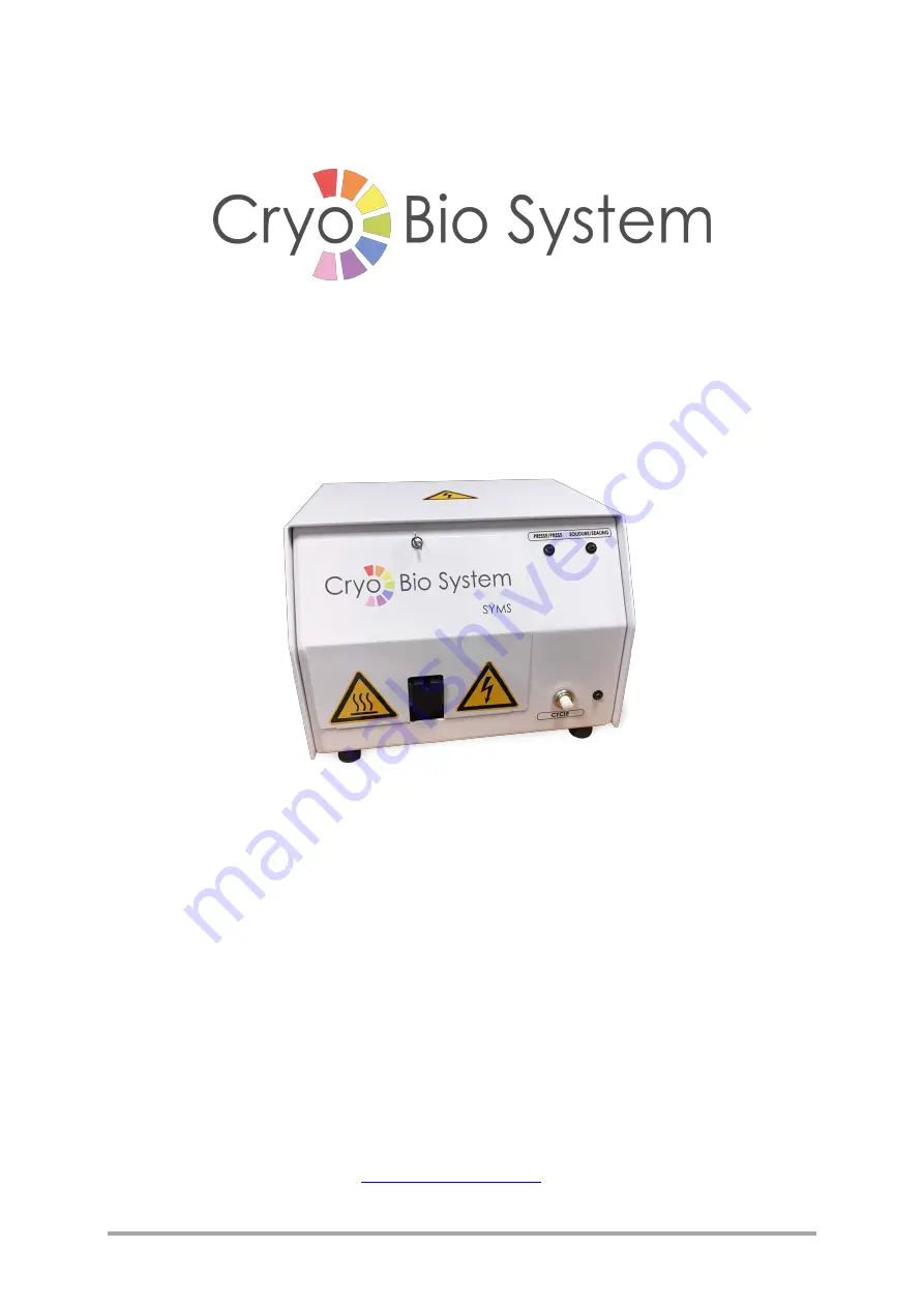
SYMS I MANUAL SEALING MACHINE
For CBS™ High Security straws and HSV High Security Vitrification straws
Read this manual carefully before using the SYMS I manual sealing machine
CRYO BIO SYSTEM
– tel +33 (0)2 33 34 64 64
Edition: 2021


