background image

     20

5.3 Waveform Generator (cont’d)

5.3.1 Login Screen – User Identification Input 

(cont’d)

Standard users are intended to be everyday users of the system, 
who only have the ability to run pre-defined pulse waveform 
protocols from an access list as determined by the administrator. 
The administrator may grant a standard user the ability to 
modify an already defined protocol, but not to add/remove 
protocols.

AgilePulse

 is factory configured with only the “admin” account 

available. By default no password is defined so the user can 
enter the system with parameters matching that of Figure 5-4 
on first login. The password may then be changed from the User 
account screen in Setup section. The most recently logged in 
user will be displayed in the User Name field on startup.

To enter User names and Passwords, touch the Change buttons 
to activate a virtual keyboard.

User name:

Enter the user’s name to login

Password:

Enter the password associated with the user 
account. Password entry is masked with “*” 
characters in order to provide increased security.

When the User name and Password have been entered, touch 
OK to log in.

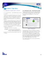
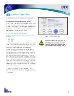
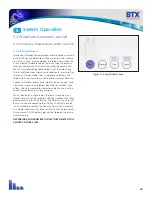
5.3.2 Welcome Screen – Identification Input

An opening screen (Figure 5-5) allows input of key experimental 
information after the initial system log in. Information is entered 
by a virtual keypad. The purpose of this screen is for the USER 
(Researcher) to enter the Experiment ID, Transfectant and 
Electrode ID.

All three parameters are set by user selected input. Touching a 
text field box highlights it blue and allows modification. Use the 
available touch screen keypad to enter up to 15 characters for 
each. Alternatively, a USB keyboard may be plugged into one 
of the front panel USB connectors and used to edit the ID fields 
manually. This screen cannot be operated from the foot pedal (ID 
fields cannot be selected or edited). The following pulse delivery 
screen may be operated by either the touch screen or by the 
optional foot pedal depending on the specification.

After verifying the identifications are correct go to the delivery 
screen by touching NEXT.

Figure 5-5: Opening Screen

System Operation

5

Summary of Contents for BTX AgilePulse ID

Page 1: ...AgilePulse ID In Vivo Gene Delivery System USER S MANUAL ...

Page 2: ...apply to you Without limiting the generality of the foregoing BTX HARVARD APPARATUS shall not be liable for any claims of any kind whatsoever as to the equipment delivered or for non delivery of equipment and whether or not based on negligence Warranty is void if the AgilePulse instrument is changed in any way from its original factory design or if repairs are attempted without written authorizati...

Page 3: ...2 PAGE 6 7 7 7 8 8 10 11 12 13 14 14 14 15 15 15 16 16 17 18 18 18 18 18 19 19 19 20 21 22 23 24 25 26 27 27 28 29 30 31 31 32 33 Table of Contents ...

Page 4: ...3 PAGE 8 9 12 12 12 14 15 16 16 16 18 19 19 19 20 21 21 22 22 22 24 25 27 28 29 Table of Contents ...

Page 5: ...ser must read this manual carefully before the instrument is placed into operation Removing the cover may void the warranty Do not connect or disconnect the high voltage cable with the high voltage enabled To connect or disconnect the cable turn line power off and unplug line mains cord Do not touch the electrode tip while the waveforms are being applied If a problem occurs during a run push the S...

Page 6: ...gned for research purposes The system has three components the AgilePulse Waveform Generator the Intramuscular Array IMA electrodes 4 6 parallel needle arrays and the User Manual Using other components may damage the system will certainly provide degraded performance and invalidate the warranty NOTE The AgilePulse Waveform Generator contains a high voltage power supply and was designed with safety...

Page 7: ...cated on the wrapper label 4 Do not under any circumstances turn the power switch off while the system is pulsing if an emergency occurs push the emergency button on the front panel 5 Do not connect or disconnect any electrode from the waveform generator when the pulse waveforms are being applied 6 Do not put your fingers or any other object on the ID electrode tip while pulse waveforms are being ...

Page 8: ...Muscle Large dose Significant pain Pain 5 6 out of 10 High cell transfection Many Many Deliver viral vector with hypodermicneedleinto muscle Muscle Immune system reacts to viral vector inefficient when boosting Pain 2 out of 10 3 1 Applications The AgilePulse system is used to deliver DNA vaccines to study the effects and potential of this application for research purposes only The AgilePulse syst...

Page 9: ...the early 1980 The routine use of electroporation became very popular with researchers through the 1980s because it was found to be a practical way to place drugs or other molecules into cells In the late 1980s scientists began to use electroporation for applications in multi cellular tissue In the early 1990 s Lluis Mir of the Institute Gustave Roussy was the first to use electroporation in a hum...

Page 10: ...ill kill cells by destroying the membrane and heating The electric field in which the cells are located is produced by two system components The first is the voltage waveform generator and the second is the electrode which converts the voltage into the electric field Neumann Sowers and Jordan 1998 pages 68 73 provides the equation that relates the transmembrane voltage TMV to electric field intens...

Page 11: ...ion FEBS Lett 256 4 10 Djuzenova C S Zimmermann U Frank H Sukhorukov V L Richter E Fuhr G 1996 Effect of medium conductivity and composition on the uptake of propidium iodide into electropermeabilized myeloma cells Biochim Biophys Acta 1284 143 152 Klenchin VA Sukharev SM Chernomordik LV Chizmadzhev YA Electricaly induced DNA uptake by cells is a fast process involving DNA electrophoresis 1991 Bio...

Page 12: ...When the pulses are delivered in less than half a second there is only one muscle contraction and tolerability is highly improved The AgilePulse system has the following waveform settings available Three groups may be used A group is 1 10 pulses with the same parameters The system software automatically concatenates each group Group Pulse Amplitude Pulse Width Pulse Interval Group Interval Pulse N...

Page 13: ...that of a parallel plate As an example the calculated electric field for two needles per row is presented below As the spacing between the rows increases the electric field rapidly falls off and cold spots form pores in the cells and vaccine delivery does not occur The AgilePulse needle electrodes are specifically designed to produce near uniform electric fields in the treatment volume There are c...

Page 14: ...53 64 Epub 2008 Sep 27 Lundberg K Roos A K Pavlenko M Wehrum D Pisa P A modified epitope identified for generation and monitoring of PSA specific T cells in patients on early phases of PSA based immunotherapeutic protocols Vaccine 2009 Mar 4 27 10 1557 65 Bråve A Hallengärd D Gudmundsdotter L Stout R Walters R Wahren B Hallermalm K Late administration of plasmid DNA by intradermal electroporation ...

Page 15: ...ll User inputs are entered via the touch screen The system may be operated by using an optional foot pedal On the back panel there is a line mains power connector The high voltage pulsing circuits are controlled by a microcontroller The microcontroller accepts user inputs from the touch screen and produces the pulse waveforms A second microcontroller is used as an independent audit of the waveform...

Page 16: ... high voltage power supply The Line Mains power switch should never be used to turn off the system in an emergency situation if pulsing is in progress 4 2 2 Back Panel On the back panel there is an IEC Power Entry module and provisions for an Ethernet port Ethernet connectivity is not currently available 4 3 Intradermal ARRAY Electrode IDA The IDA consists of two parts the handle and the tip The h...

Page 17: ...ower should illuminate and the Login Screen should appear within 10 seconds If the Waveform Generator power switch fails to illuminate then return it to the OFF position O Verify the power cord is properly plugged into the wall Verify the wall socket is functional If necessary you may need to check the fuse on the back panel of the Waveform Generator If it is faulty replace it with the exact type ...

Page 18: ... or mild detergent with warm water and a soft lint free paper or cloth towel Do not apply the cleaning solution directly to the screen to avoid liquid running into other parts of the cabinet Put a small amount of cleaner on the towel and gently rub the screen Avoid hard rubbing abrasives or harsh solvents like alcohol or ammonia AgilePulse System Components Set Up 4 ...

Page 19: ...at a later time from the log files 5 1 1 USB Key Memory Stick The USB key can be inserted into either of the two USB ports that are located on the front panel of the waveform generator It should be inserted before delivering pulses and can be removed at any time after the saving data message disappears The USB key may be removed without performing any additional procedures The data logs that resul...

Page 20: ...accine is ready for administration remove the protective cover from the IDA Tip taking care not to disconnect the tip from the handle 5 3 Waveform Generator 5 3 1 Login Screen User Identification Input After power is turned on a Login Screen is presented that requires the user to enter a user name and password combination The Login system is designed to prevent unauthorized users from accessing th...

Page 21: ...ccount Password entry is masked with characters in order to provide increased security When the User name and Password have been entered touch OK to log in 5 3 2 Welcome Screen Identification Input An opening screen Figure 5 5 allows input of key experimental information after the initial system log in Information is entered by a virtual keypad The purpose of this screen is for the USER Researcher...

Page 22: ... in ohms is displayed This number is the effective resistance of the animal s skin and will continue to be updated every second Figure 5 6 Delivery Screen Initialization Figure 5 7 Delivery Screen Load Estimation 3 If the LOAD Reading is within range Less than 3500 ohms for skin then the next step is to turn on the high voltage power supply by touching the READY button or depressing the foot pedal...

Page 23: ...creen 5 When the system reaches a shutdown state either by successful waveform delivery or by error all buttons will turn solid green and pulse delivery data will be displayed in the System message text box The load message box will change from the estimated load value to the actual high voltage pulse monitored value 6 All run history log data are automatically stored in internal Flash Memory as w...

Page 24: ...onstructed in a AgilePulse Log Year Month Day Time hierarchy A maximum of 20 000 delivery logs can be stored in the internal system memory Raw Data CCEP Date Time xml Text Log CCEP Date Time log CSV Data CCEP Date Time csv Start and Stop Date Start and Stop Time Experiment Transfectent Electrode ID Process Completion Type Set Pulse Parameters Average monitor pulse voltage Average monitor pulse cur...

Page 25: ...val programmed to waveform generator IntMon Pulse interval monitored by independent time auditor system Date Start 8 14 2011 6 00 09 AM 8 14 2011 1 00 09 PM GMT Experiment Pl Transfectant Plasmid A Electrode IDA 2001 Operator BTX Final Completion Code Code 0 Success Start 8 14 2011 6 00 09 AM 8 14 2011 1 00 09 PM GMT Process Completion Return Code 0 Success Pulse VSet PVMon PIMon RMon DurSet DurMo...

Page 26: ...tandard comma separated file primarily meant to be imported into Microsoft Excel for further user manipulation As an example in Figure 5 12 a user chart was made to display the monitored amplitude samples of three 100 microsecond pulses run at 5 kHz In this case each pulse contains eight amplitude samples Figure 5 12 Sample Amplitude Analysis System Operation 5 ...

Page 27: ...ltage above maximum voltage 16 High volt power supply maximum current draw 17 Pulse voltage monitor detected off zero voltage while no pulse was active 18 Pulse voltage monitor below maximum droop specification 19 Pulse voltage monitor above maximum overshoot specification 20 Pulse current monitor below minimum specification 21 Pulse current monitor above maximum specification 22 Independent time ...

Page 28: ... assigned read only access to all of the pulse protocol waveforms on the system The administrator may then select individual protocols and provide more access by giving both read and write privileges or they may restrict access to a protocol altogether by giving the user no access at all When a user is not given any protocol access they will not be able to see or select it from the Protocol screen...

Page 29: ...evious level of hierarchy Special time folders display basic information on the right hand side of the screen when selected Identification numbers time of day and status completion indicators help the user find the correct vaccine delivery run to download When selected by a single tap on the touch screen icon any level of hierarchy can be saved to a USB Key inserted in the front panel by pressing ...

Page 30: ...justed protocol is saved to internal memory when the HOME button is pressed Minimum and maximum parameter values are as follows Protocol Parameter Boundaries Amplitude volts Duration ms Interval ms Pulse Pulse Groups Minimum 50 0 050 0 200 5 kHz 1 1 Maximum 1000 10 1000 1 Hz 10 3 For Pulse Amplitudes greater than 300V the maximum allowable Pulse Width is 1ms Pulse duty cycle is limited to 50 Cauti...

Page 31: ...e user believes that there is a defect in the BTX product the customer should contact BTX Technical Support at 800 272 2775 or email techsupport btx harvardapparatus com If the system needs to be returned to BTX please contact Technical Support for a Return Material Authorization RMA number Customer Service 6 ...

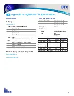
Page 32: ...specialist Pulse parameters Download data files Delivery Electrode Vaccine Delivery Volume 2 blebs x 40 µl each IDA 4 6 2 blebs x 45 µl each IDA 4 6 2 blebs x 50 µl each IDA 6 6 Skin dermis Electrode Reusable with alcohol cleaning Sterile Single packaged Disposable IDA 4 4 2 IDA 4 6 2 IDA 6 6 2 Row Spacing 4 mm 4 mm 6 mm Needles row 4 6 6 Needle Spacing 1 5 mm 1 5 mm 1 5 mm Needle Diameter 0 3 mm ...

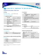
Page 33: ...omatically stored in internal memory and may be downloaded to an external USB Key Maximum Data Logs stored and retrievable from internal flash memory 20 000 Front Panel Computer Operating System Windows Mobile 6 0 Interface Touch screen Line Mains Switch with illumination Emergency Stop Button resets computer to ready state Touch Screen USB Ports 2 Electrode connector Fischer Series 4032 Back Pane...

Page 34: ...tibility Directive 2011 65 EU RoHS Compliant Standard s to which conformity is declared Safety IEC 61010 1 2010 3rd Edition Emissions Immunity EN 61326 1 2013 FR47 FCC Part I5 Sub Part B 2011 EN 61000 4 2 1995 A1 1998 A2 2001 EN 61000 4 3 2002 EN 61000 4 4 2004 EN 61000 4 5 1995 A1 2001 EN 61000 4 6 2007 EN 61000 4 11 2004 EN 61000 3 2 2000 EN 61000 3 3 1995 A1 2001 CISPR11 2003 A1 2004 Group 1 Cl...

Reviews: