APEX
™
Exciter Incorporating FLO
™
Technology
Details of the System Setup Screens
Navigating the LCD Display Screens
26
04s30
0.fm
03/08/07
888-2604-001
Page: 3-41
WARNING: Disconnect primary power prior to servicing.
3.6.3.4
RTAC Off Air Mode
An RTAC Off-Air Mode parameter gives the customer the option of having the exciter's
correction in the hold or bypass mode when the exciter is power up but off line.
• In bypass mode RTAC settings are discarded when exciter is off line and RTAC must
re-adapt when the exciter is switched back on line.
• In the hold mode, the current correction is stored when the exciter goes off line and is
used as a starting point for RTAC when it goes back on line.
3.6.4
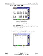
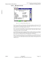
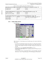
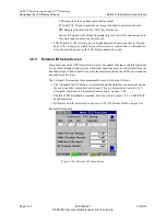
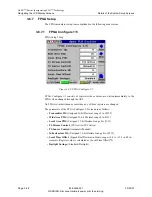
Display Setup Screen
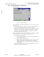
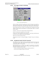
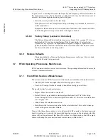
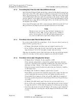
DisplaySetup.bmp
Figure 3-35 Display Setup Screen
The following ia a list of entries on the System setup screen.
• Date: Enter the current date.
• Time: Enter the correct time.
The exciter will keep track of the date and time, even during periods of power loss,
and display the date and time at the bottom of all screens except the Power Up screen.
• Screen Saver: (Range is 1 to 30 minutes) Enter the length of time (on the LCD display
numeric key pad) required for the screen to go blank if it is not used.
• Display Invert: When the Display Invert box is pressed, a sub window appears. Press-
ing Done in the sub window causes the display to be inverted if Enabled is showing
and to be upright if Disabled is showing.
• Chart Source: Determines source of Main screen spectrum response display. Choices
are:
Tx-Pre HPF: From rear panel RF sample input, labeled PA Sample.
Tx-Post HPF: From rear panel RF sample input, labeled HPF Sample.
FLO Ref: The FLO I and Q signal from the FPGA board.
C: The FLO real signal from the FPGA board.
D: The sample of the linear precorrector output.

