


APEX
™
Exciter Incorporating FLO
™
Technology
Navigating the LCD Display Screens
Details of the System Setup Screens
Page: 3-34
888-2604-001
03/08/07
WARNING: Disconnect primary power prior to servicing.
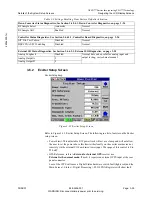
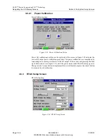
Exciter Setup, See Section 3.6.2, Exciter Setup Screen, on page 3-35.
Max Mod Crest Factor
13dB
See technical manual
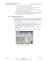
Exciter Setup RTAC, See Section 3.6.3, RTAC Setup Screen, on page 3-38.
Max Stretch
3.0dB
See technical manual
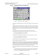
RTAC Off-Air mode
Bypass
Bypass or Hold, customer’s choice
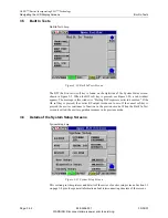
Display Setup, See Section 3.6.4, Display Setup Screen, on page 3-41.
Page Title
Apex Exciter
Customer’s choice
Screen Saver
30 minutes
Customer’s choice
Display invert
Disabled
Customer’s choice
Chart Source
TX-Post HPF
Normal, but customer’s choice to change.
LCD Contrast
50%
Normal, but customer’s choice to change.
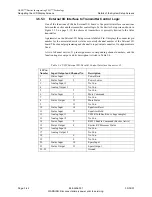
External I/O Setup, See Section 3.6.5, External I/O Setup Screen, on page 3-42.
VSWR F/B Low Threshold
0.0V
0.25V is normal, but customer’s choice.
VSWR F/B High Threshold
5.0V
Normal, but customer’s choice.
VSWR F/B Level
100%
70% is common, but customer’s choice.
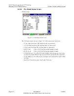
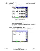
RF Present Cutoff
10mW
50% of normal exciter output power.
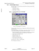
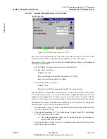
Serial Setup page 1, RS 232 Front and Rear, See Section 3.6.6.1, Serial Setup Screen 1 of 3, RS-232, on page
3-45.
Baud Rate
57600
Choice of several, see technical manual
Parity
None
See technical manual
Data Bits
8
See technical manual
Stop Bits
1
See technical manual
Flow
None
See technical manual
Protocol
Harris
See technical manual
Serial Setup page 2, Ethernet, See Section 3.6.6.2, Serial Setup Screen 2 of 3, Ethernet, on page 3-46.
MAC Address
00-00-00-00-00-00
See technical manual
IP address
000.000.000.000
See technical manual
Gateway Address
000.000.000.000
See technical manual
Subnet Mask
000.000.000.000
See technical manual
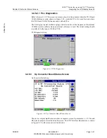
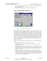
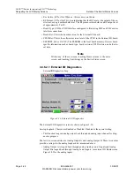
Adaptive Processing Status Diagnostics, See Section 3.4.3.1, Adaptive Processing Diagnostics, on page 3-11.
Loopback
None
Normal
Test Tone
Disabled
Normal
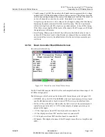
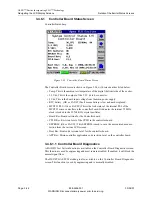
System Control Status Diagnostics, See Section 3.4.6.1.1, Controller Board Diagnostics, on page 3-26
CAN Test Messages
Disabled
Normal
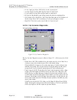
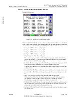
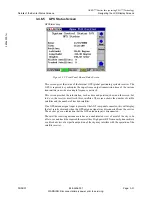
Up converter Status Diagnostics, See Section 3.4.5.3.1, Up Converter Diagnostics, on page 3-22
Output Power AGC
Enabled
Normal, can be disabled for testing
Table 3-3 Settings Resulting From Restore Defaults Activation.


