APEX
™
Exciter Incorporating FLO
™
Technology
Navigating the LCD Display Screens
Details of the System Setup Screens
Page: 3-42
888-2604-001
03/08/07
WARNING: Disconnect primary power prior to servicing.
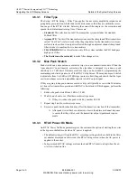
J: The sample of the non linear precorrector output.
FLO w/RTAC: Digital signal taken at output of adaptive precorrector board.
BIT: Sample of the Built In Test FIFO (for future use).
Exciter: RF signal is taken from J4 sample output of exciter PA and connected to
J4 sample input on down converter board.
• LCD Contrast: A 100% setting gives a bright but washed out screen that is still read-
able. A 0% setting gives a dark screen of relatively low contrast that is still readable.
Enter the desired percent on the LCD display numeric key pad.
3.6.5
External I/O Setup Screen
Some functions of the APEX digital exciter must be capable of being controlled (operated)
via a parallel remote control system while other functions must be controllable from the
transmitter logic. The External I/O board is the interface between the APEX exciter and the
transmitter control logic.
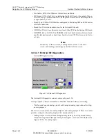
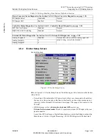
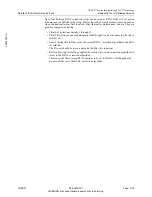
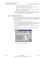
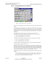
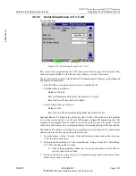
The External I/O screen has three programable areas, which are as follows.
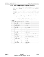
• The “Channel Pin I/O Function” represents the parallel interface connections between
the exciter and the transmitter control logic. They are discussed in Section 3.6.5.3,
External I/O Interface to Transmitter Control Logic, on page 3-44
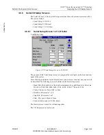
• The three VSWR foldback parameters are discussed in Section 3.6.5.1, VSWR Fold-
• RF Present Cutoff is discussed in Section 3.6.5.2, RF Present Cutoff, on page 3-43
ExternalIOSetup.bmp
Figure 3-36 External I/O Setup Screen

