APEX
™
Exciter Incorporating FLO
™
Technology
Theory of Operation
APEX Exciter Analog Assembly Overview
Page: 4-8
888-2604-001
03/08/07
WARNING: Disconnect primary power prior to servicing.
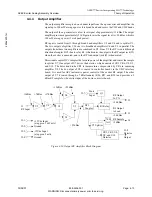
Power output capability of the exciter is 100 mW average power.
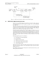
The down converter sequentially selects the RF feedback samples from the transmitter
system and converts them down to the 11.1 MHz 1st IF frequency. This signal is sent to the
ADC (analog to digital converter) board.
The UDC interface sends commands and control signals from the digital assembly
controller board to the down converter, PLL, up converter boards, and output amplifier and
receives status signals from them.
4.4.1
Up Converter Board Block Diagram Description
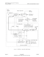
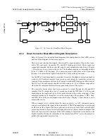
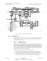
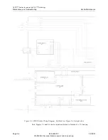
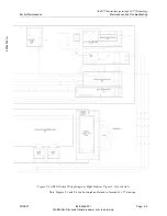
Refer to Figure 4-5 for a simplified block diagram of the up converter.
The up converter receives the 11.1 MHz 1st IF signal from the DAC and heterodynes it up
to a 140 MHz 2nd IF frequency. The conversion requires a 128.9 MHz CW signal from the
1st LO (local oscillator) circuit on the PLL board.
The 2nd conversion stage of the up converter heterodynes the 140 MHz 2nd IF signal to the
on channel frequency, using a CW signal from the 2nd LO circuit in the PLL board.
The 2nd local oscillator is injected on the high side of the channel for VHF channels and
on the low side of the channel for the UHF channels.
The output of the up converter is a low level on channel signal. This signal is sent to the
output amplifier.
4.4.1.1
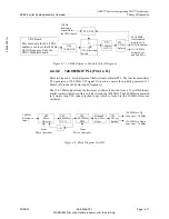
Up Converter Board UHF/VHF Band Pass Filter
The type of filter used depends on the operating channel.
In UHF units, an inter digital comb-line band pass filter is used to filter out the mixer image
and other unwanted signals. This filter has two tunable sections. A voltage tunable
bandpass filter to pass the on channel signal, this is referred to a “TuneB” in the Up
Converter Diagnostics screen. It also has a voltage tunable notch filter to reject the local
oscillator, this is referred to as “TuneA” in the Up Converter Diagnostics screen. When a
UHF channel is selected, the filter is automatically tuned to the correct frequency for that
channel. The TuneA and TuneB options in the Up Converter Diagnostics screen allow the
two filters to be retuned for testing purposes.
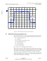
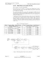
Low band VHF channels 2 - 6 have the local oscillator, 2nd IF frequency and image above
the channel, therefore, an elliptic low pass filter with a cutoff frequency of 100 MHz is
used for the low band filter. This filter that is capable of passing channels 2 through 6 with
low group delay while still rejecting the required signals.
High band VHF channels 7-13 have the local oscillator and image above the channel and
the 2nd IF frequency below the channel. For this group of channels, a bandpass filter is
required. This is a fixed bandpass filter that is capable of passing channels 7 through 13
with low group delay while still rejecting the required signals.

